Signal Processing Concepts with ADALM-MMSC
Attention
This is a work in progress
Overview
This document provides a practical introduction to signal‑processing concepts using the AD4080, the ADALM2000, and the MMSC board. It combines theoretical explanations with interactive Python scripts to demonstrate frequency‑domain analysis, oversampling, digital filtering, and noise behavior in a real mixed‑signal measurement setup.
The focus is on FFT‑based analysis, sinc filter behavior, and integrated noise effects, allowing users to validate theoretical expectations through direct measurement. All scripts referenced in this tutorial are available in the associated repository.
User Guides
Using the Detect Sample Frequency Script
To run the sampling frequency detection (Fs Detect) script, begin by powering up both the ADALM2000 and the MMSC board equipped with the MAX32666FTHR microcontroller.
Connect the W1 output from the ADALM2000 to the negative input (IN–) on connector P17 of the MMSC board. Ensure that all ground connections are correctly made. Configure the appropriate COM port on the host computer to establish communication.
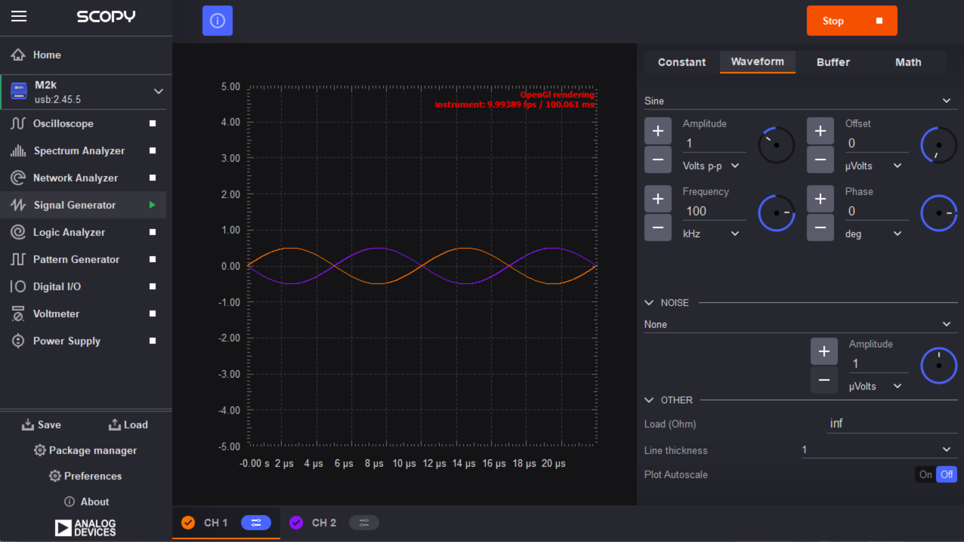
Next, run the Fs Detect script using Python. Open Scopy, navigate to the Signal Generator, and configure a sine-wave output. The default input frequency is typically 100 kHz, but this value may be adjusted as needed. Start the signal generator to apply the sine-wave input to the ADC.
Scopy Sample Setup
In the script’s graphical interface, enter the input frequency into the provided text box. Data acquisition is controlled using the following buttons:
Run → Begins continuous accumulation of ADC samples
Stop → Halts acquisition
Single Shot → Captures one buffer of data and stops
The script identifies the FFT bin containing the dominant spectral peak and calculates the ADC sampling frequency from its location. The calculated value is compared to the expected sampling frequency reported by the hardware, and the error percentage is displayed.
Expected Output
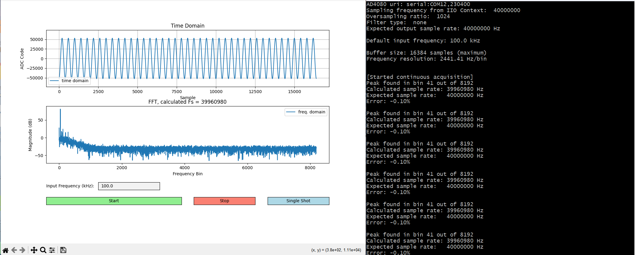
Adjusting the physical clock on the AD4080 board causes the ADC sampling frequency to change. This shift is reflected in the FFT output and calculated sampling frequency in real time.
Using the Frequency Sweep Script
To run the frequency sweep script, begin by connecting the ADALM2000 and the AD4080 evaluation board to your computer. Ensure that the correct USB interfaces and serial communication ports are specified in the script arguments. The front‑end sampling frequency must match the rotary switch setting on the AD4080 board—this is typically 40 MHz.
Once the hardware is powered and connected, run the script using Python. The graphical interface will launch automatically, providing user‑configurable input fields for sweep parameters including:
Start frequency
Stop frequency
Step size
OSR (Oversampling Ratio)
Additionally, the interface offers radio buttons to select the desired digital filter type.
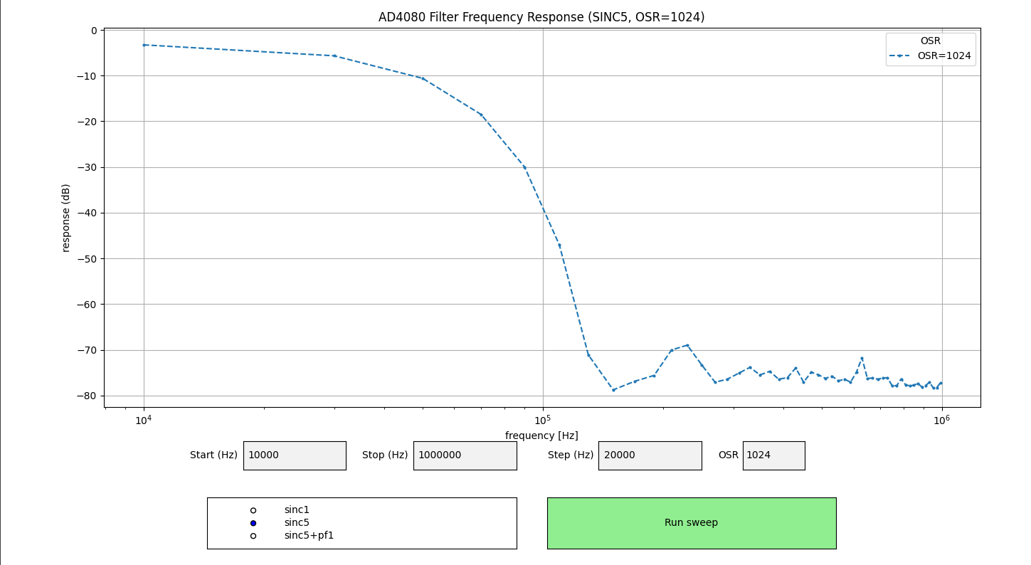
Pressing the Run sweep button initiates the automated frequency sweep. During operation, the interface displays the Filter frequency response.
Expected Output
Using the AD4080 Sink Script
To run the AD4080 sink script, begin by connecting the ADALM2000 and the AD4080 evaluation board. Ensure the correct USB and serial communication ports are selected.
Once the script is launched, configure:
Fundamental frequency
Signal amplitude (dBFS)
Tab to change parameters
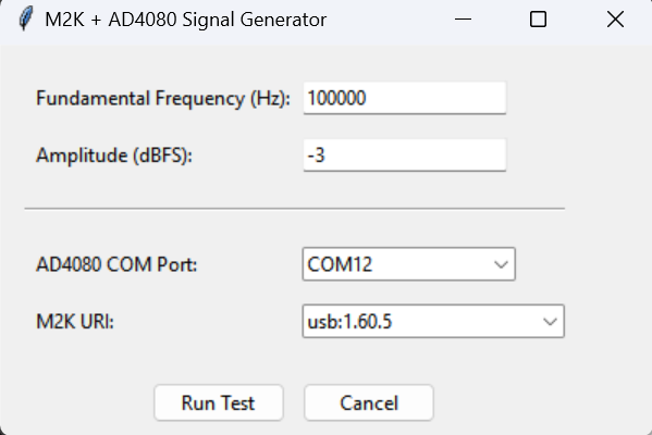
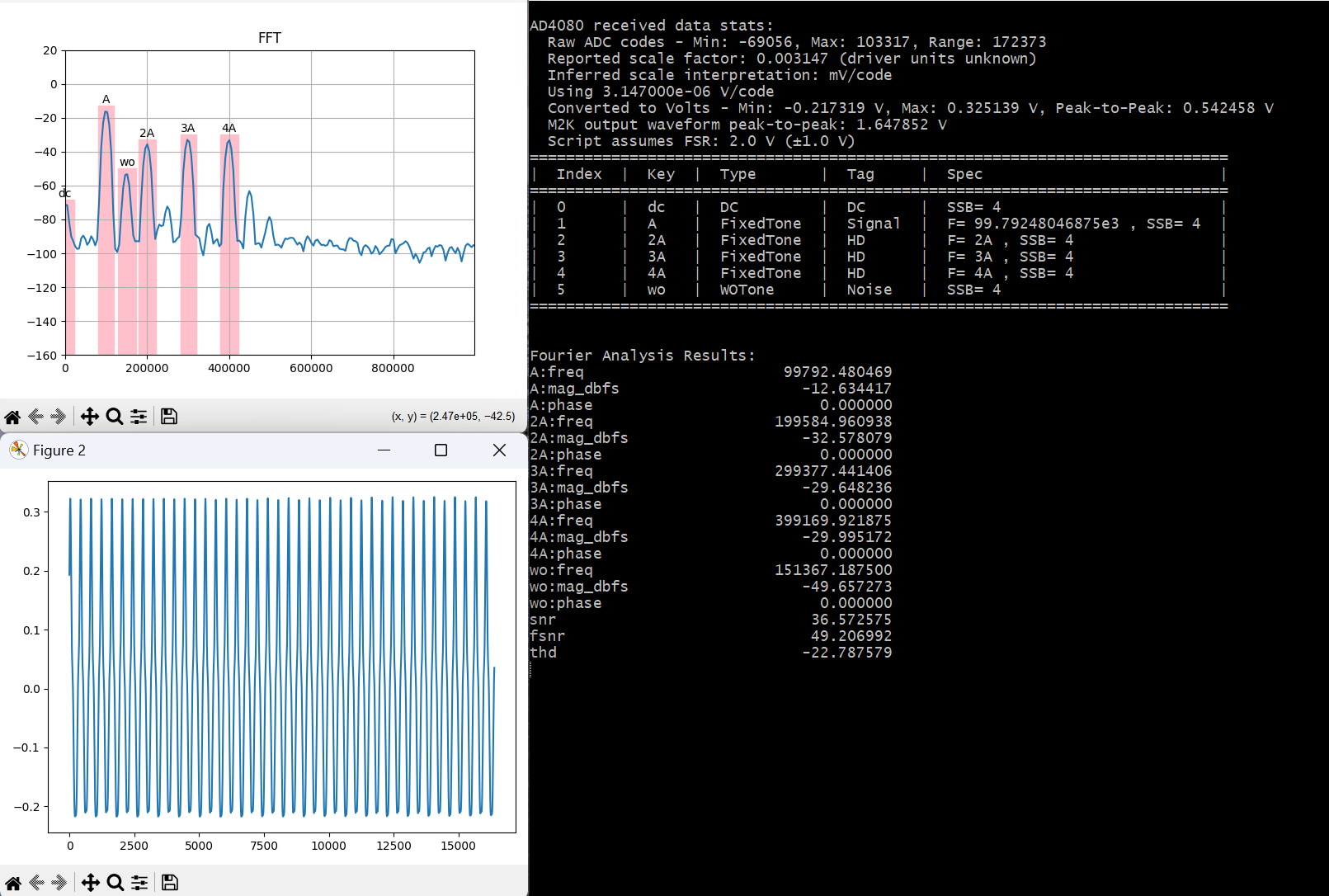
After configuration, the ADALM2000 generates a waveform containing a fundamental tone, harmonics, and noise. The AD4080 captures ADC samples, which are converted to voltage units, normalized to full scale, and analyzed using FFTs.
Expected Outputs
Using the Interactive Sinc Folding Script
To run the Interactive Sinc Folding script, connect the ADALM2000 and AD4080 evaluation board. Select the appropriate serial port and LibIIO URI.
The interface allows real‑time adjustment of:
Decimation ratio (OSR)
Digital filter type
Noise bandwidth
Noise spectral density
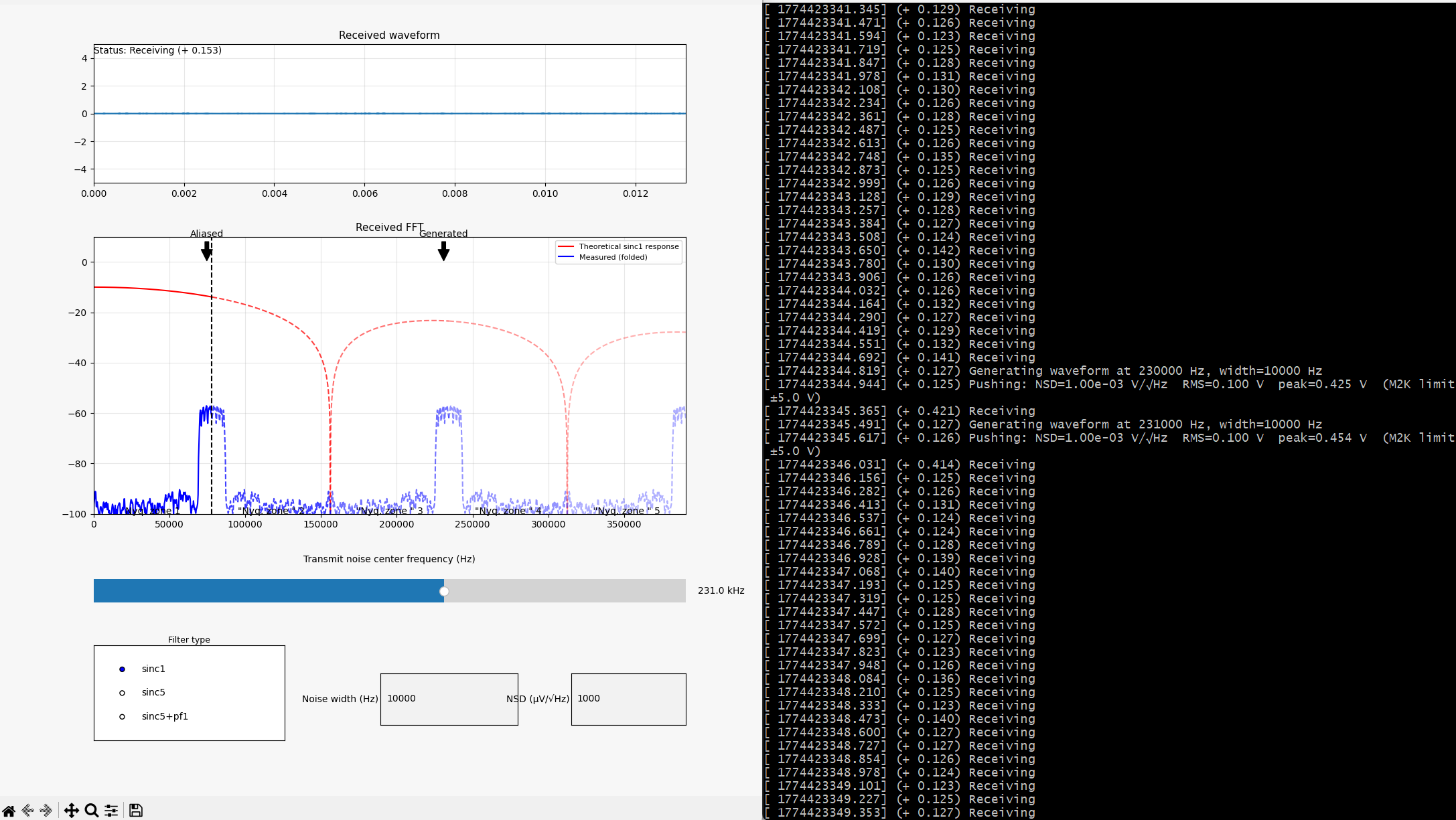
The frequency‑domain display updates in real time, showing how noise folds into the baseband and how digital filtering shapes the spectrum.
Using the Noise Sweep Script
To run the noise bandwidth sweep script, connect the ADALM2000 and AD4080 and verify the front-end sampling frequency.
The script increments noise bandwidth from DC, captures ADC samples, removes DC offset, and computes RMS noise using the standard deviation.Thegraphical interface will launch automatically, providing user‑configurable input fields for sweep parameters including:
Start frequency
Stop frequency
Step size
OSR (Oversampling Ratio)
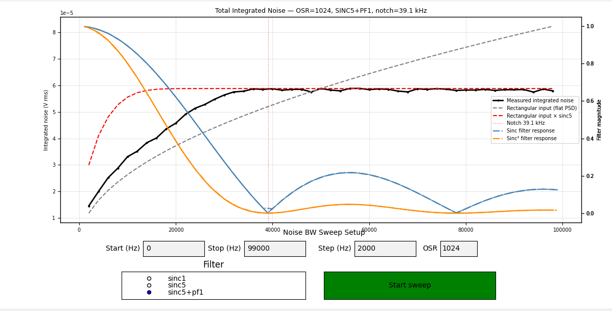
Measured results are overlaid with analytical reference curves derived from ideal sinc‑filter responses.
Developer Overview
FFT Fundamentals
The Fast Fourier Transform (FFT) converts time‑domain samples into a frequency‑domain representation, revealing sinusoidal components, harmonics, and noise.
The frequency resolution is:
\(\Delta f = \frac{f_s}{N}\)
The frequency represented by bin \(k\) is:
\(f_k = \frac{k}{N} \cdot f_s\)
If the input frequency is known, the sampling frequency can be estimated as:
\(f_s = \frac{f_{in} \cdot N}{k}\)
Sinc Folding Concepts
Oversampling ADCs use sinc‑based digital decimation filters with repeating lobes and nulls. As the output rate is reduced, energy outside the baseband folds back according to the sinc filter response, producing predictable spectral shaping.
Higher‑order sinc filters provide stronger attenuation but introduce more pronounced shaping. Increasing OSR reduces bandwidth and increases noise suppression while moving folding points closer together.
Integrated Noise in Oversampled ADCs
Wideband noise is spectrally shaped by sinc filters before integration. The observed RMS noise depends on the magnitude‑squared filter response and the effective noise bandwidth.
Examining integrated noise behavior reveals how oversampling, filter selection, and decimation affect noise performance.
Developer Guide
The scripts implement FFT‑based spectral analysis, frequency sweeping, and noise integration using consistent assumptions about sampling frequency, decimation, and normalization.
DC offsets are removed before noise calculation
RMS noise is computed using standard deviation
Analytical reference curves assume ideal rectangular noise shaped by sinc filter responses
This approach allows direct comparison between theoretical expectations and measured ADC behavior.
Help and Support
For support related to hardware setup, script execution, or data interpretation:
Review the script repository documentation
Consult the AD4080, ADALM2000, and MMSC user manuals
Contact your Analog Devices applications support representative
Documentation authored by Raya Norelle Mangahas, Spring Intern 2026