ROS2 Integration with IIO Devices
This tutorial walks you through running a servo motor control demo using the adi_iio ROS2 package. You will use Docker to run the demo nodes, inspect the ROS2 system with standard CLI tools, and explore how the code maps IIO attributes to ROS2 topics and services.
Note
The adi_iio package handles low-level IIO communication, while
application nodes interact with devices through standard ROS2 interfaces.
No direct libiio knowledge is required.
Hardware Prerequisites
Raspberry Pi 5 running ADI Kuiper Linux
ADALM-LSMSPG board connected to the Raspberry Pi via the 40-pin ribbon cable
Note
This demo simulates servo motor control using readings from the AD5592r and AD5593r. No actual servo motor hardware is required — the demo generates position commands and reads ADC feedback to demonstrate the ROS2/IIO integration pattern.
Software Prerequisites
Docker and Docker Compose installed on the Raspberry Pi
Clone the adi_ros2 repository and build the base Docker image:
analog@analog:~$ git clone https://github.com/analogdevicesinc/adi_ros2.git
analog@analog:~$ cd adi_ros2
analog@analog:~/adi_ros2$ docker compose -f compose.build.yml build base
Clone the iio_ros2 repository and checkout the
adalm-lsmspg-examplebranch (contains the ADALM-LSMSPG example):
analog@analog:~$ git clone -b adalm-lsmspg-example https://github.com/plescaevelyn/iio_ros2.git
Architecture Overview
The ROS2 architecture separates device communication from application logic:
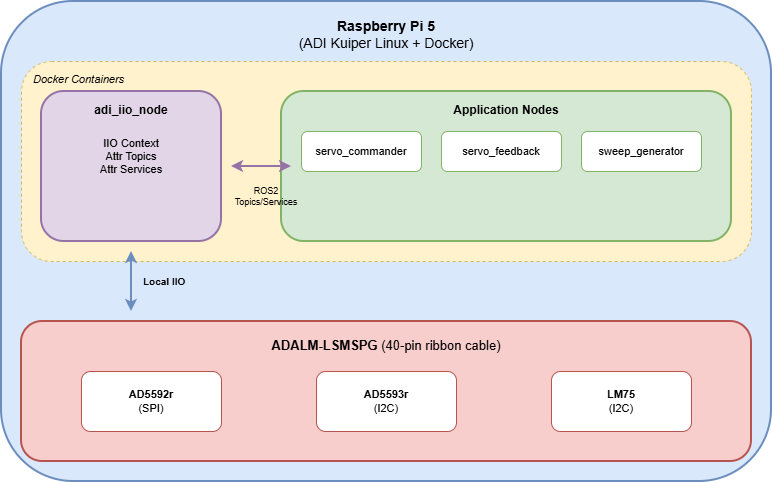
The adi_iio_node acts as a bridge between the IIO subsystem and ROS2. It
connects to the ADALM-LSMSPG via the local IIO backend and exposes each device
attribute as either a ROS2 topic (for continuous streaming) or service (for
on-demand reads/writes). This allows application nodes to interact with the
hardware using standard ROS2 patterns — no direct IIO knowledge required.
The demo simulates a servo control loop: sweep_generator publishes position
commands, servo_commander converts them to DAC values and writes to the
AD5592r, and servo_feedback reads ADC values to simulate position/current
sensing.
Step 1: Verify the Hardware
Before running ROS2, confirm that the ADALM-LSMSPG is properly connected and the IIO devices are accessible. The Raspberry Pi should be running ADI Kuiper Linux with the ADALM-LSMSPG overlay configured (as described in the earlier sections of this tutorial).
Run iio_info to verify the IIO context:
analog@analog:~$ iio_info -u local:
You should see the ad5592r, ad5593r, and lm75 devices listed. If
not, check that the device tree overlay is enabled and the ribbon cable is
properly connected.
Step 2: Build the Docker Image
The demo runs inside Docker containers, which bundle ROS2, the adi_iio
package, and all dependencies. This ensures a consistent environment without
needing to install ROS2 natively on the Raspberry Pi.
Navigate to the example directory and build the image:
analog@analog:~$ cd iio_ros2/examples/adalm_lsmspg/docker
analog@analog:~/iio_ros2/examples/adalm_lsmspg/docker$ docker compose build
This creates a Docker image containing:
The
adi_iioROS2 package — provides the IIO-to-ROS2 bridge nodeThe
adalm_lsmspgexample package — contains the servo demo nodesRuntime dependencies — libiio, numpy, and scipy
Step 3: Run the Demo
Launch the demo using Docker Compose:
analog@analog:~/iio_ros2/examples/adalm_lsmspg/docker$ docker compose up
This command reads the compose.yml file and starts two containers. Let’s
look at what it does:
services:
  adi_iio:
    # ... build configuration ...
    command: ros2 run adi_iio adi_iio_node --ros-args -p uri:="ip:analog.local"

  demo:
    # ... container configuration ...
    depends_on:
      - adi_iio
    command: >
      bash -c "sleep 3 && ros2 launch adalm_lsmspg adalm_lsmspg_bringup.launch.py"

  shell:
    # ... interactive shell for debugging (profiles: [debug]) ...
The adi_iio service starts first, launching the adi_iio_node which
connects to the IIO context at ip:analog.local. The demo service waits
3 seconds for adi_iio_node to initialize, then launches the application
nodes via the bringup launch file. The shell service is only started when
using the debug profile (docker compose --profile debug up).
Once running, you will see log output from all the nodes. The adi_iio_node
initializes first, connecting to the IIO context and discovering the devices.
Then the application nodes start: sweep_generator begins publishing position
commands, servo_commander writes DAC values, and servo_feedback reads
ADC values and publishes feedback.
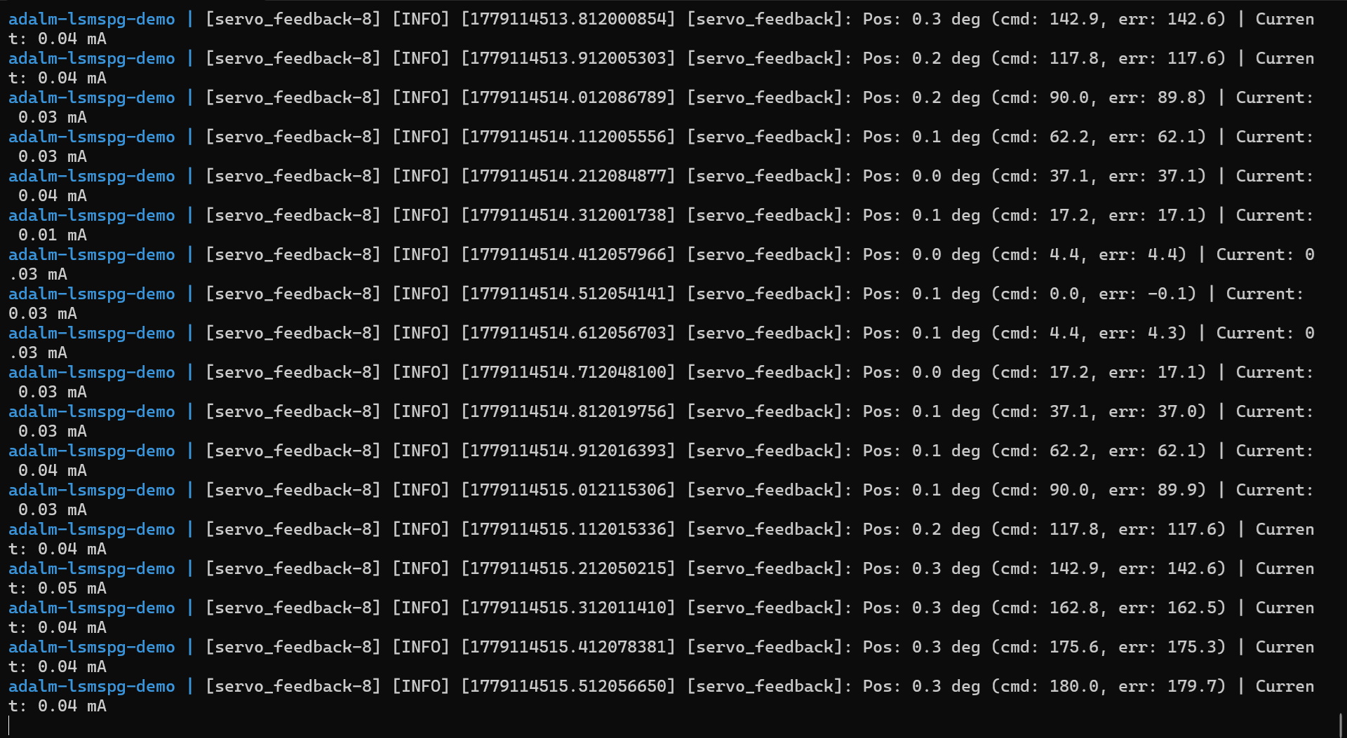
The demo runs continuously, sweeping the simulated servo position back and forth. Leave this terminal running and open a new one for the next step.
Step 4: Inspect the ROS2 System
With the demo running, we can use standard ROS2 command-line tools to inspect the system. Open a new terminal and start a shell inside the Docker environment:
analog@analog:~/iio_ros2/examples/adalm_lsmspg/docker$ docker compose run --rm shell
This drops you into a container with ROS2 tools available. First, list the active nodes to see all the running components:
root@analog:/# ros2 node list
You should see four nodes: /adi_iio_node (the IIO bridge) and the three
application nodes (/servo_commander, /servo_feedback, /sweep_generator).
Next, list the available topics. The adi_iio_node creates topics for each
IIO attribute, and the application nodes create their own topics for the servo
control loop:
root@analog:/# ros2 topic list
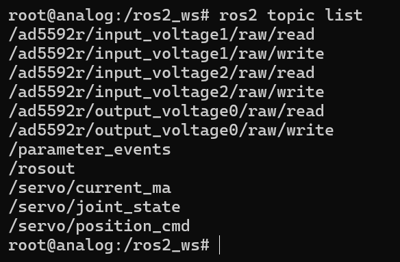
Notice the IIO attribute topics like /ad5592r/input_voltage1/raw — these
are automatically generated by adi_iio_node for each channel. The
application topics like /servo/position_cmd and /servo/position_feedback
are created by the demo nodes.
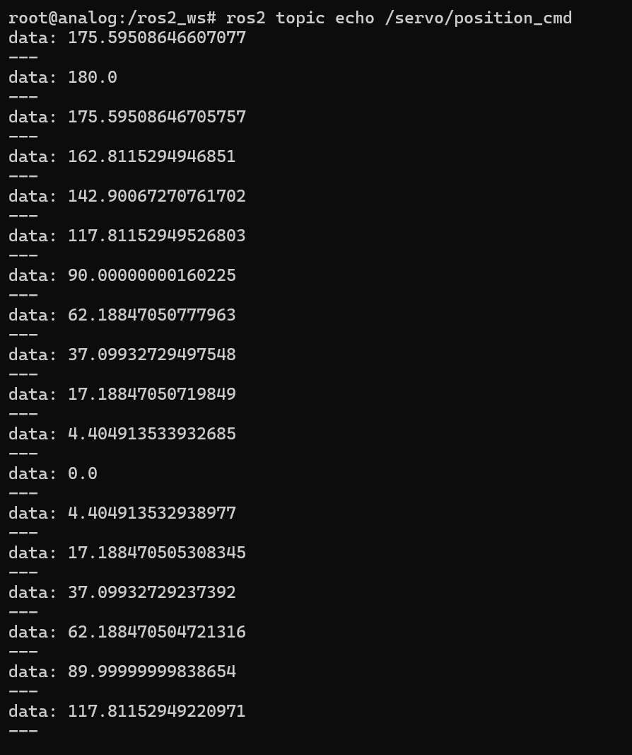
To see live data, echo one of the feedback topics. This shows the simulated
position values being published by servo_feedback:
root@analog:/# ros2 topic echo /servo/position_feedback
You can also interact with IIO attributes directly using ROS2 services. For example, read the temperature from the LM75 sensor:
root@analog:/# ros2 service call /adi_iio_node/AttrReadString adi_iio/srv/AttrReadString \
    "{attr_path: 'lm75/input_temp0/raw'}"
This demonstrates that any ROS2 node can access IIO device attributes without
needing to know anything about libiio — the adi_iio_node handles all the
low-level communication.
Step 5: Cleanup
When finished, stop the demo by pressing Ctrl+C in the terminal running
docker compose up, or run the following from another terminal:
analog@analog:~/iio_ros2/examples/adalm_lsmspg/docker$ docker compose down
This stops and removes the containers. The Docker images remain cached for faster startup next time.
How the Code Works
The servo demo consists of three application nodes, each implemented as a Python ROS2 node. The source code is located in examples/adalm_lsmspg/adalm_lsmspg/.
sweep_generator — Position Command Generation
The sweep_generator node
(sweep_generator.py)
generates a sinusoidal position sweep from 0 to 180 degrees and publishes to
the /servo/position_cmd topic. The core logic computes the angle using a
sine wave:
def timer_callback(self):
    self.time_elapsed += self.timer_period

    mid = (self.min_angle + self.max_angle) / 2.0
    amplitude = (self.max_angle - self.min_angle) / 2.0
    angle = mid + amplitude * math.sin(2 * math.pi * self.sweep_rate * self.time_elapsed)
This produces smooth oscillation between the configured minimum and maximum angles. The sweep rate (default 0.5 Hz) and update rate (default 10 Hz) are configurable via ROS2 parameters.
servo_commander — DAC Output Control
The servo_commander node
(servo_commander.py)
subscribes to position commands and writes corresponding DAC values to the
AD5592r. It demonstrates two key IIO service interactions:
Reading the DAC scale factor — Before writing values, the node reads the scale attribute to convert millivolts to raw DAC counts:
def read_scale(self):
    request = AttrReadString.Request()
    request.attr_path = self.get_parameter('dac_scale').value
    future = self.attr_read_string_client.call_async(request)
    future.add_done_callback(self.scale_response_callback)
Enabling topic-based writes — The node enables a write topic for the DAC raw attribute, allowing it to publish values directly:
msg = AttrEnableTopic.Request()
msg.attr_path = self.get_parameter('dac_raw').value
msg.loop_rate = self.loop_rate
self.attr_enable_topic_client.call_async(msg)
Converting angle to DAC value — When a position command arrives, the node converts degrees to millivolts, then to raw DAC counts:
def angle_to_voltage_mv(self, angle_deg: float) -> float:
    """Convert angle (degrees) to voltage (mV)."""
    normalized = (angle_deg - self.min_angle) / (self.max_angle - self.min_angle)
    normalized = max(0.0, min(1.0, normalized))
    return normalized * self.max_voltage_mv

def position_callback(self, msg: Float64):
    # ...
    voltage_mv = self.angle_to_voltage_mv(angle)
    raw_value = min(4095, max(0, int(voltage_mv / self.scale)))
servo_feedback — ADC Input Reading
The servo_feedback node
(servo_feedback.py)
reads ADC values from the AD5592r to simulate position and current feedback.
It subscribes to IIO attribute topics for continuous streaming:
self.position_raw_sub = self.create_subscription(
    String,
    f"{self.get_parameter('position_adc_raw').value}/read",
    self.position_raw_callback,
    self.qos,
)
self.current_raw_sub = self.create_subscription(
    String,
    f"{self.get_parameter('current_adc_raw').value}/read",
    self.current_raw_callback,
    self.qos,
)
The node converts raw ADC readings to physical units (degrees and milliamps)
and publishes them as JointState messages:
pos_voltage_mv = self.position_raw * self.position_scale
measured_angle = self.voltage_to_angle(pos_voltage_mv)

cur_voltage_mv = self.current_raw * self.current_scale
measured_current = self.voltage_to_current(cur_voltage_mv)

joint_msg = JointState()
joint_msg.header.stamp = self.get_clock().now().to_msg()
joint_msg.name = ['servo_joint']
joint_msg.position = [measured_angle * 3.14159 / 180.0]
joint_msg.effort = [measured_current]
self.joint_pub.publish(joint_msg)
IIO Service Interface
The key interaction with IIO happens through the adi_iio_node services:
AttrReadString— Read an attribute value (e.g., scale factors)AttrEnableTopic— Enable streaming for an attribute (creates a<attr_path>/readtopic for inputs or<attr_path>/writefor outputs)AttrDisableTopic— Disable streaming for an attribute
This pattern allows any ROS2 node to interact with IIO devices using standard ROS2 communication patterns. The application nodes never call libiio directly — they simply publish/subscribe to topics and call services, making it easy to integrate precision analog hardware into robotic systems.
Comparison: ROS2 vs. Python/MATLAB
Aspect |
Python (pyadi-iio) |
MATLAB |
ROS2 |
|---|---|---|---|
Use case |
Scripting, testing |
Analysis, plots |
Robotics, control |
Architecture |
Single process |
Single process |
Distributed nodes |
Real-time |
No |
No |
Soft real-time |
Deployment |
Direct |
MATLAB runtime |
Docker/native |
Integration |
Python ecosystem |
MATLAB toolboxes |
ROS2 ecosystem |
ROS2 is the right choice when the IIO device is part of a larger robotic or automation system that requires distributed processing, standardized communication, or integration with other ROS2 packages (navigation, control, perception, etc.).