AD-FMCOMMS11-EBZ Hardware
The AD-FMCOMMS11-EBZ is built around the AD9162 RF DAC and the AD9625 RF ADC. For detailed specifications and datasheets, refer to the respective product pages.
Schematic, PCB Layout, Bill of Materials
AD-FMCOMMS11-EBZ Design & Integration Files
Schematic
PCB Layout
Bill of Materials
Allegro Project (get the Allegro FREE Physical Viewer; you need 16.5 or higher).
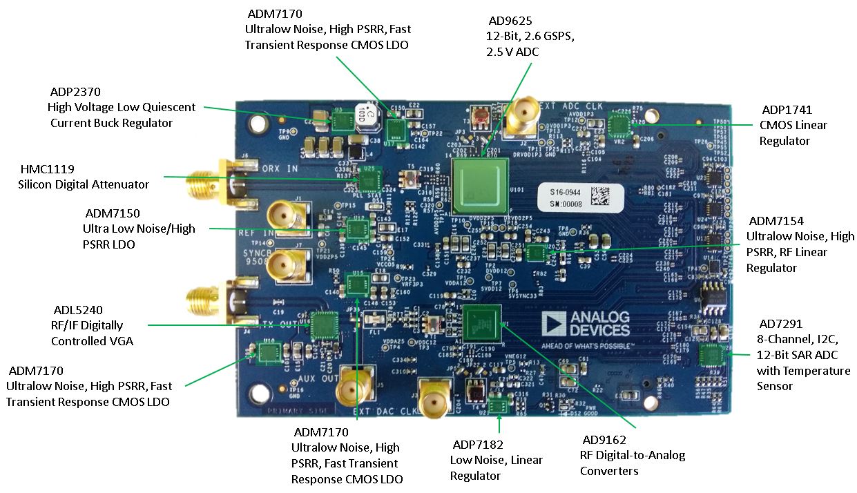
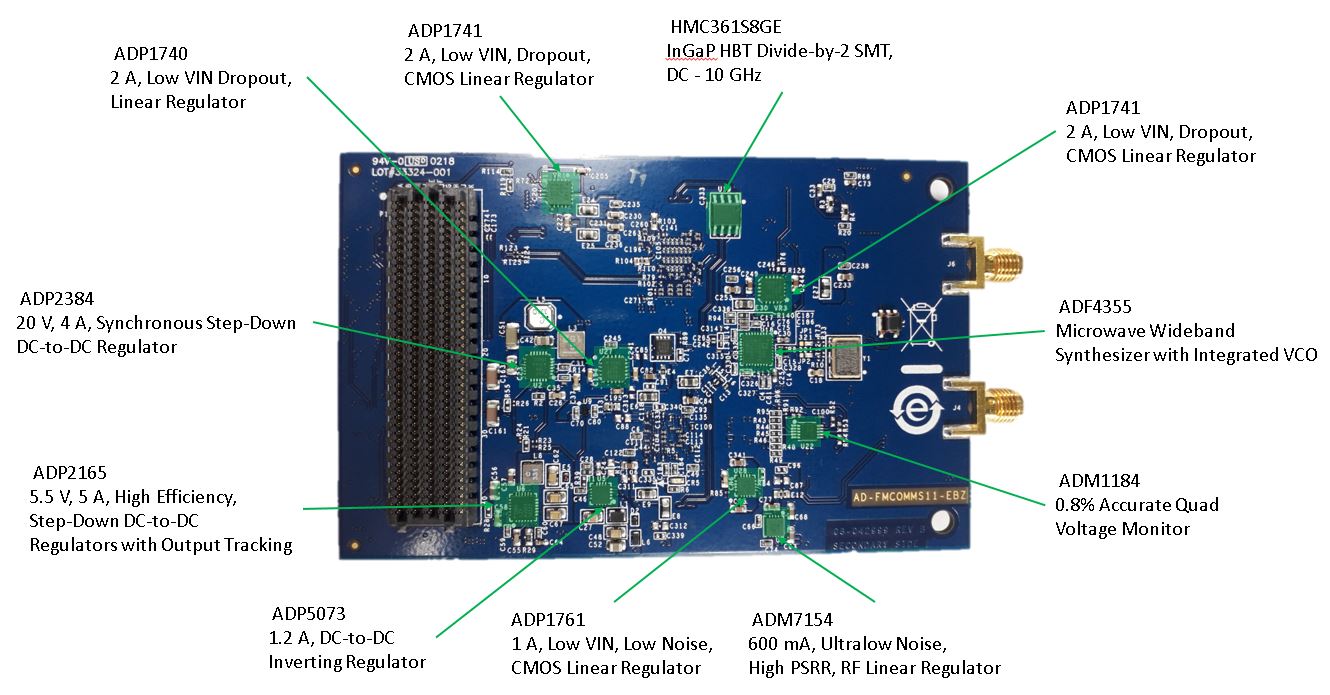
Picture and Main components
Top Layer Main components
Bottom Layer Main components
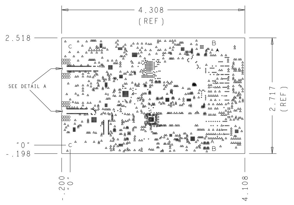
Outline
For those that don’t want to load up the Allegro viewer, here is a basic outline/component placements of the board. The PCB measures 100mm x 62mm and is the same form factor as the RFSOM
Size
The size of the board (not including the SMA connectors, which project beyond the edge of the board) is 110mm x 69mm. The mounting holes align with the carrier card (EK-Z7-ZC706-G), and are shown below.
Layers
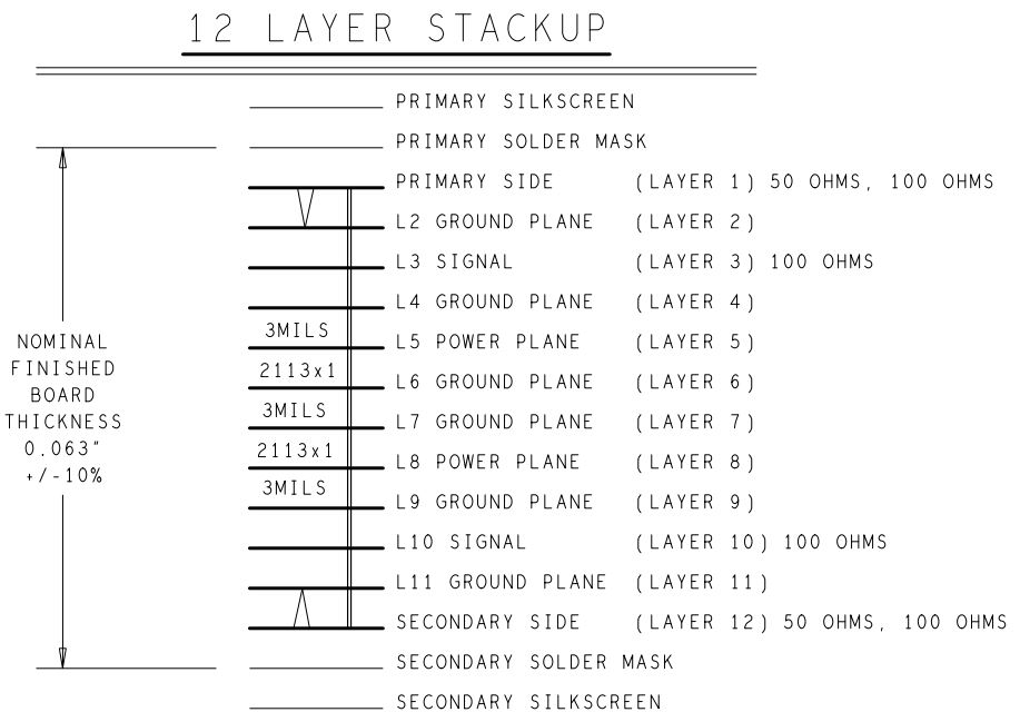
The AD-FMCOMMS11-EBZ is a 12 layer board.