ADRV-PACKRF Production Testing
Overview
Production tests for the ADRV-PACKRF BOX are composed of a series of Bash scripts that run on both the Raspberry Pi and the Device Under Test (DUT). The tester interacts only with the Raspberry Pi through a keyboard and monitor. An HDMI display connected to the Raspberry Pi shows information about tests, required tester actions, and results.
Assembly is split into two phases (Partial Assembly and Full Assembly). After each assembly phase, the corresponding testing batch must be run.
If a test fails, the testing sequence stops and a FAILED message is printed. The tester can identify which component failed and then either repeat the test or mark the device as defective.
A set of log files is created and stored on the Raspberry Pi SD card for supervising the testing process.
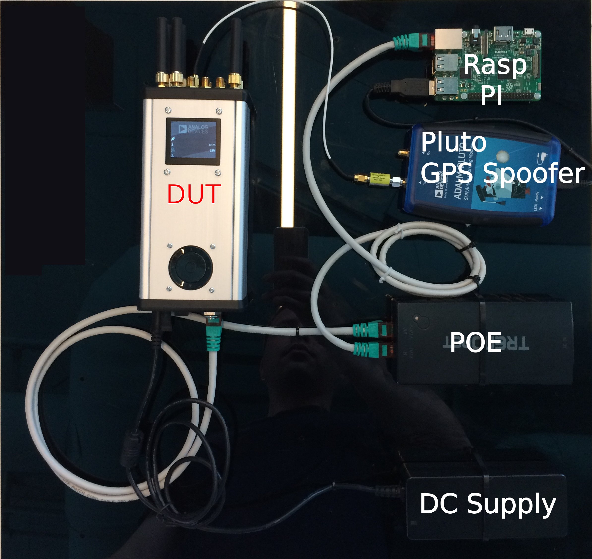
Required hardware
1 PACKRF box with microSD card prepared for PACKRF
1 Raspberry Pi with microSD card prepared for Raspberry Pi
1 5V micro USB power supply for Raspberry Pi
1 DC wall wart (12V, 3A)
1 POE Injector BOX
2 Ethernet cables (one Raspberry Pi ↔ POE Injector Data IN, one POE Injector Data OUT ↔ PACKRF)
1 USB media drive with type A to micro OTG adapter
1 SMA ↔ SMA loopback cable
1 pair of CTIA standard headphones with media buttons
1 loopback TRRS jack
1 ADALM PLUTO (for GPS spoofing)
1 SMA DC blocker
Test setup
Complete the Partial Assembly of the radio.
Connect an HDMI monitor to the Raspberry Pi.
Connect a USB keyboard to the Raspberry Pi.
Connect an Ethernet cable between the Raspberry Pi and the radio.
Note
The Ethernet port of the Raspberry Pi is configured with a static IP and a DHCP server is running on it. Do not connect anything other than the POE Injector or the RFSOM-BOX.
Connect a 5V power supply to the “PWR IN” port of the Raspberry Pi.
Power on the Raspberry Pi. Once booted, the testing screen should be visible on the monitor.
Connect the DC wall wart adapter and POE Injector to the SOM-BOX PCB.
PACKRF SD card
The SD card image used for production testing is the same as the one prepared for shipping. To create it, follow the Zynq & Altera SoC Quick Start Guide and the “User Space Tools” sub-section on the same page.
Raspberry Pi SD card
The SD image is based on Raspbian Stretch with desktop. The setup_env.sh
script must be run to prepare the testing framework.
Write a clean Raspbian Stretch with desktop image to a minimum 8GB SD card:
Download: Raspbian latest
Write it following: Installing Pi images
Boot the Raspberry Pi with the newly created card and establish an internet connection via Ethernet or WiFi.
Download the test framework repository from git and save the folder in
/home/pi/.Open a terminal, change directory to
/home/pi/rfsom-box-production-test, and run:./setup_env.sh rfsom-box jig
After the script finishes, disconnect the Ethernet cable from the Pi and reboot. The Pi should display the test screen on boot.
Step 1 — Partial Assembly Test
This test sequence can only be started once Partial Assembly is complete.
The following items are tested:
Power supply voltage output
Charging, Battery
Ethernet
USB
Real Time Clock
UART communication with GPS module
Audio CODEC and Audio Connector
Test procedure
Insert the PACK-RF SD card in the carrier card slot.
Connect the DC adapter barrel power connector.
Connect the Ethernet cable from the POE injector.
Press and release the power button.
Wait for the system to boot up. The following screen should be visible on the test station display.
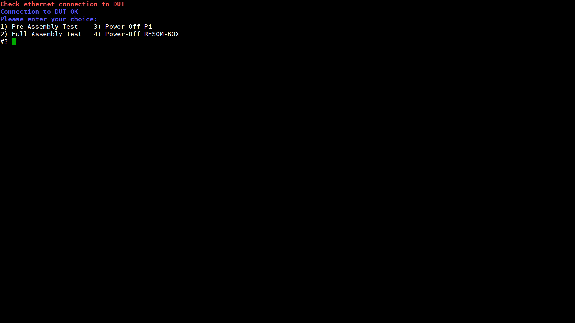
Select option 1 to begin “Pre Assembly Test”.
Communication with the DUT is established and the test starts. If connection cannot be established, a “Check Ethernet connection to DUT” warning is displayed.
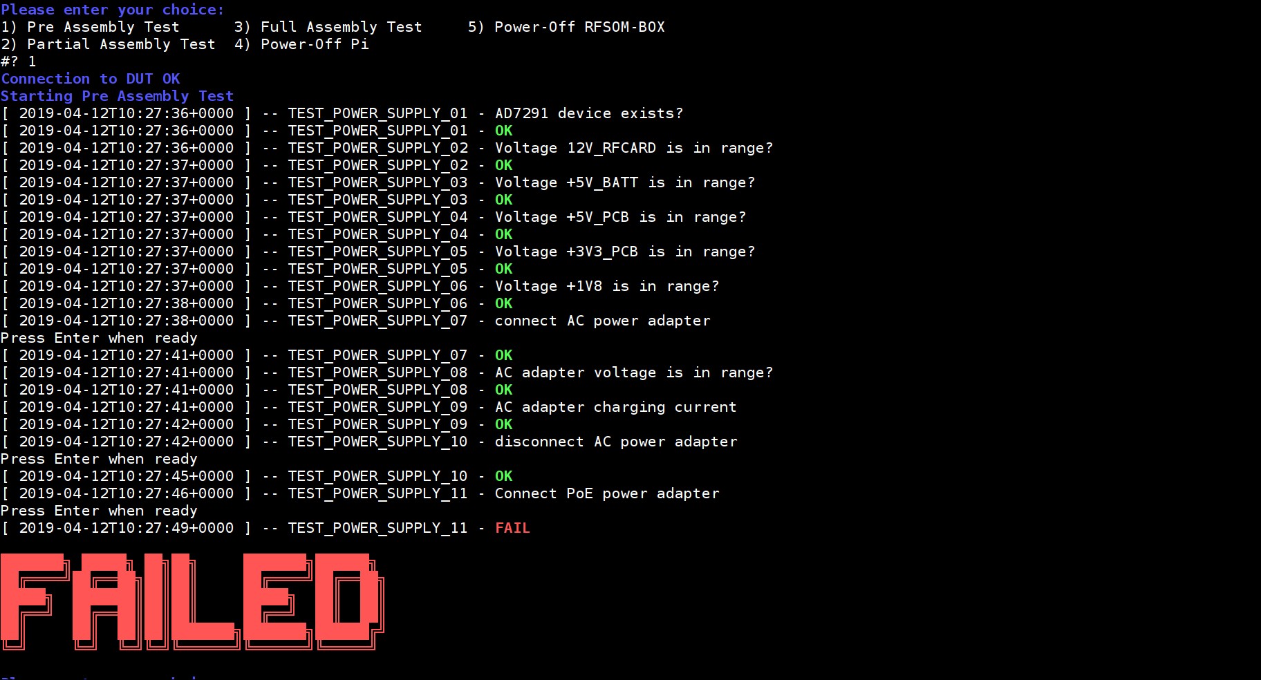
A log is printed on the display while the test runs. The image below shows a case where POE supply testing failed.
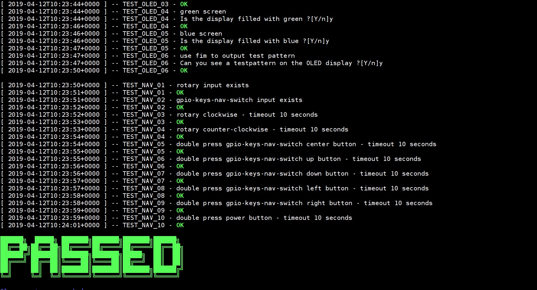
If all required tests pass, the following message is displayed.
Whether the test passed or failed, the selection menu is displayed. Power off the RFSOM-BOX by entering 4 in the selection menu.
Continue with Full Assembly.
Step 2 — Full Assembly Test
This test sequence can only be started once Full Assembly is complete.
The following items are tested:
RF front-end (Transmit and Receive with SMA connectors)
Inertial Measurement Unit
GPS Satellite Locking (PLUTO GPS spoofer required)
Display
Navigation Switch / Rotary Encoder
Test procedure
Press and release the BOX power button.
Wait for the system to boot up. The “Analog Devices” screen should be visible on the box screen.
From the test selection screen select option 2. Full assembly testing starts.
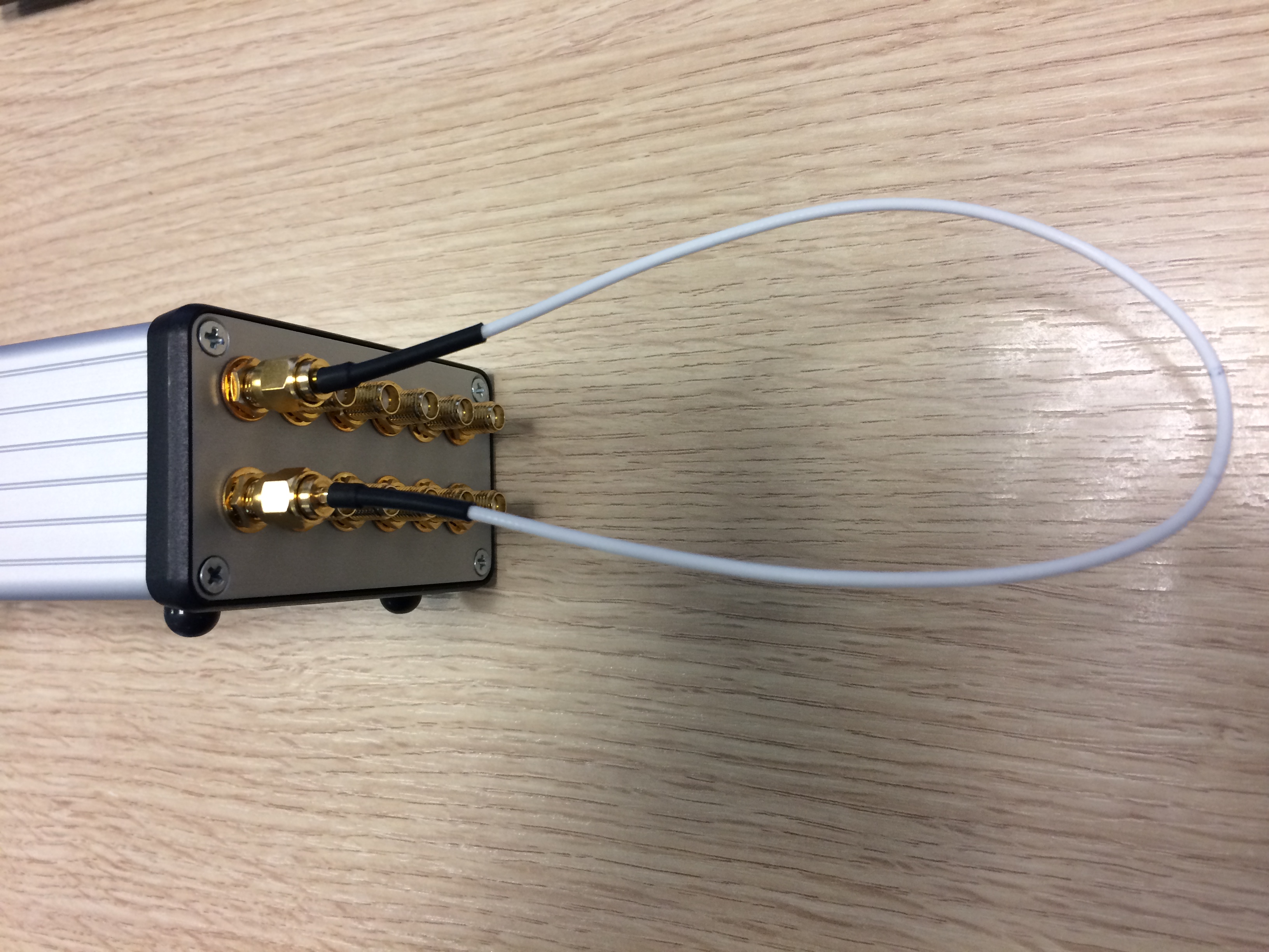
RF testing requires making connections between different SMA connectors using the SMA ↔ SMA loopback cable.
After all nine connections have been tested, the RF test result should look as shown below.
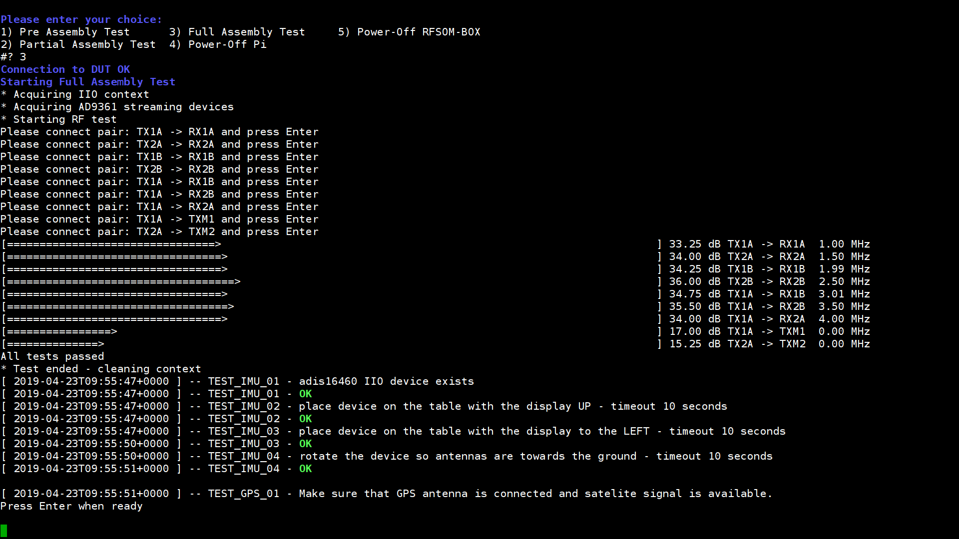
If any pair failed, check whether cables are bad, connections are bad, or cables are swapped.
IMU testing requires physically moving the RFSOM-BOX.
GPS module testing requires an ADALM PLUTO connected through a DC block and SMA ↔ SMA cable to the GPS port of the DUT. The PLUTO generates GPS signals and the DUT must acquire location, speed, and time. Locking has a 120 second timeout — if no lock is acquired, the test fails.
After testing finishes and the PASSED/FAILED state is displayed, power off the RFSOM-BOX by selecting option 4.
PackRF assembly and testing is now complete.