ADRV9009 and ADRV9009-ZU11EG JESD Parametrization
HDL
If the desired design has a configuration other than the default one, some modifications to the HDL and devicetree are required.
First, check that the project is parametrized for this flow by verifying the MAX_TX/RX/RX_OS_NUM_OF_LANES variable in common/adrv9009zu11eg_bd.tcl.
If that condition is met, skip to the last step in this section.
Otherwise, configure the AXI_XCVR IP with MAX_TX/RX/RX_OS_NUM_OF_LANES
instead of TX/RX/RX_OS_NUM_OF_LANES. Check for the ad_xcvrcon
function call and use it with a partial lane map as in this example:
ad_xcvrcon util_adrv9009_som_xcvr axi_adrv9009_som_tx_xcvr axi_adrv9009_som_tx_jesd {0 1 2 3 4 5 6 7} core_clk_a {} $MAX_TX_NUM_OF_LANES {0 1 4 5}
This gives the util the maximum number of lanes, but only binds those in the partial lane map (the last list). The lane map (first list) must contain all lanes; the order may differ depending on hardware configuration and FMC connections.
After making the modifications above, build with:
make TX_JESD_L=4
ADRV9009 Transceiver Evaluation Software
Download the transceiver evaluation software from the Transceiver Evaluation Software page, under the ADRV9008/ADRV9009 Evaluation Software with GUI for Evaluation Board section.
On the first page of the configuration panel, set the device to ADRV9009, the desired device clock frequency, the channels to enable, and the profile for each channel.
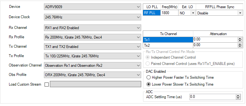
Figure 1 ADRV9009 Transceiver Evaluation Software — configuration panel
Move to the JESD204b Setup tab. Select the lanes to use in the design, keeping in mind that the lanes must correspond to those chosen in HDL.
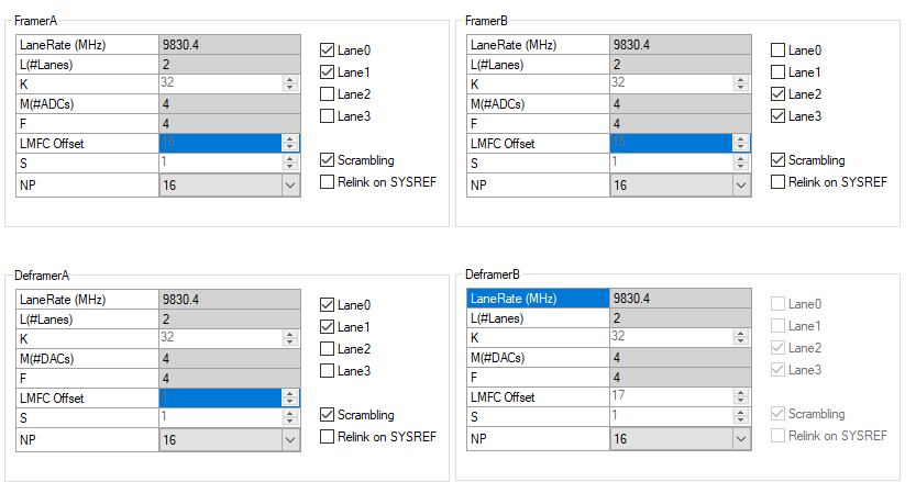
Figure 2 ADRV9009 Transceiver Evaluation Software — JESD204b Setup tab
From the top left corner, click Tools → Create Script → Init .c Files.
A success message confirms that a .c file has been generated containing
values that correspond to the devicetree setup.
Devicetree
Create a new .dts file whose name includes the number of lanes in use
(e.g. zynqmp-adrv9009-zu11eg-tx-l4.dts), then include the devicetree
file that is normally used. All that remains is to overwrite the JESD
parameters that differ, according to the .c file generated by the
evaluation software.
Example for adrv9009-zu11eg-tx-l4.dts:
#include "zynqmp-adrv9009-zu11eg-revb-adrv2crr-fmc-revb-jesd204-fsm.dts"
&spi0 {
    trx0_adrv9009: adrv9009-phy@0 {
        /* JESD204 */

        /* JESD204 OBS */
        adi,jesd204-framer-b-m = <4>;

        /* JESD204 TX */
        adi,jesd204-deframer-a-deserializer-lanes-enabled = <0x03>;
    };
    trx1_adrv9009: adrv9009-phy-b@1 {
        /* JESD204 */

        /* JESD204 OBS */
        adi,jesd204-framer-b-m = <4>;

        /* JESD204 TX */
        adi,jesd204-deframer-a-deserializer-lanes-enabled = <0x03>;
    };
};
The parameters overwritten here control the TX number of lanes and the RX_OS number of converters. Because TX and RX_OS share the same clock, it is recommended to use the same M value for both.