Data Streaming
Remote data streaming to and from hardware is made available through system object interfaces , which are unique for each component or platform. The hardware interfacing system objects provide a since class to both configure a given platform and move data back and forth from the device.
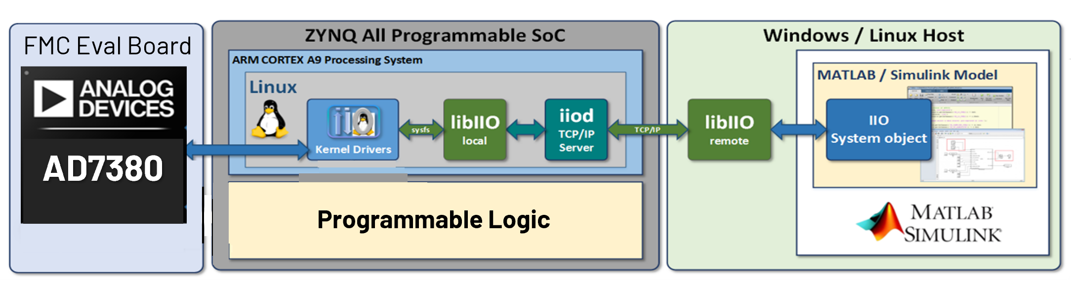
Command and control of hardware from MATLAB is accomplished by leveraging the IIO drivers built into the target platform’s kernel and libiio which provides remote backends to control drivers across different backends. Backends can be Ethernet/IP/USB based. Below is a diagram of the different components in the stack for a setup targeting the evaluation of the AD7380, but the setup will be nearly similar for other ADCs as well.
Since libiio is cross-platform it can be used from Windows, Linux, or macOS based systems. It is also a lower level library independent of MATLAB, so when moving toward production or untethered systems similar APIs that are used in MATLAB can be used in C, C++, Python, or other languages.
Connecting and Configuration
Connecting to hardware is done by setting the uri property of the system object interface. The uri for libiio always has the convention “< backend >:< address >”, where backend can be ethernet, ip or usb. address will be specific to the backend. This is documented in the libiio API .
Below is a basic example of setting up a generic ADC using an Ethernet/IP backend:
rx = adi.ADxxxx.Rx;
rx.uri = 'ip:analog.local';
data = rx();
With the code above, the hardware is not contacted until the operator or step method is called on line 3. Therefore, any properties that are set or defined before line 3 are not applied or updated on the hardware until after line 3. However, after line 3 has completed the object will become locked and certain configuration changes cannot be applied after this point. These will primarily sample rates and buffer sizes.
The state of the object follows the flow of the diagram below triggered by line 3 above.
Once the object becomes locked it must be released if the sample rate or buffers need to be modified. This will disconnect from the hardware:
rx.release(); % Release object
To provide a complete example we can do more advanced configuration like so to demonstrate property changes:
rx = adi.ADxxxx.Rx;
rx.uri = 'ip:analog.local';
rx.SamplesPerFrame = 1024;
rx.SampleRate = 256000;
data1 = rx();

% Update tunable property
rx.SampleRate = 128000;
data2 = rx();

% Update non-tunable property
rx.release();
rx.SamplesPerFrame = 4096;
dataLargerBuffer = rx();
Receiving Data
To receive or capture data from a given device first you must instantiate that device’s interface class. For a generic ADC, this would be as follows:
rx = adi.ADxxxx.Rx;
Once instantiated you can configure the number of samples to be captured by setting the property SamplesPerFrame.
rx.SamplesPerFrame = 1e6;
SamplesPerFrame is the number of samples per channel which will be captured. If your device produces complex data (I and Q) this is the number of complex samples. There will be a limit to the maximum samples which can be collected. By default this is set to 2^20, but it may be possible to make it larger depending on hardware. Once the operator methods are used for a give instantiation, the object will become locked and the SamplesPerFrame property cannot be changed. This is known as a non-tunable property.
To actually collect the samples or perform the capture, the operator of the system object should be used or the step method as so:
data = rx(); % Operator method
data = rx.step(); % Step method
Both method calls are equivalent, and the produced matrix data will be of size [SamplesPerFrame x length(EnabledChannels)]. EnabledChannels determines the channels which data will be collected from. EnabledChannels is a [1xN] vector with indexes starting at 1 of the desired channels.
Continuous Data Acquisition
If you are capturing multiple frames or buffers of data, then there might arise situations where discontinuities appear in the samples, when plotted.
Some detail and tips are discussed in this wiki page on IIO System Considerations, Tips and Tricks
The IIO buffer size is governed by the SamplesPerFrame property of the System Object classes. The kernelBuffersCount is also a property defined for the classes, and can be modified.