ZCU102 Quickstart
This guide provides step-by-step instructions on how to set up the AD9694-500EBZ on:
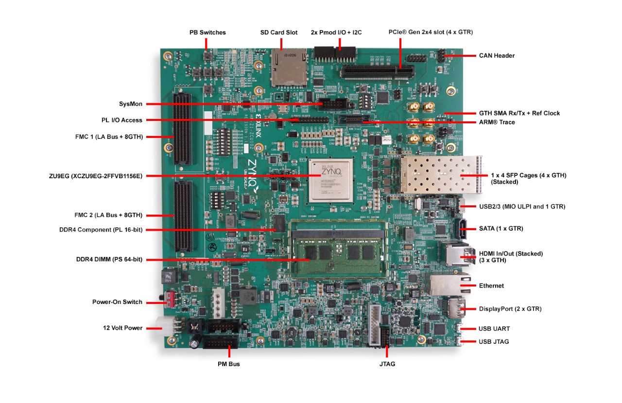
ZCU102 on FMC HPC1
All the products described on this page include ESD (electrostatic discharge) sensitive devices. Electrostatic charges as high as 4000V readily accumulate on the human body or test equipment and can discharge without detection. Although the boards feature ESD protection circuitry, permanent damage may occur on devices subjected to high-energy electrostatic discharges. Therefore, proper ESD precautions are recommended to avoid performance degradation or loss of functionality. This includes removing static charge on external equipment, cables, or antennas before connecting to the device.
Using Linux as software
Necessary files
Note
Pre-built files for this reference design are not yet available. The files must be built manually using the links above. Official release artifacts will be provided here once available. For now, check: Build an HDL project and Build the Linux kernel
The following files are needed for the system to boot:
HDL boot image:
BOOT.BINLinux Kernel image:
ImageLinux device tree:
system.dtb
They are manually generated by following the instructions below.
Instructions on how to manually build the boot files from source can be found here:
AD9694-FMC HDL project build documentation. More HDL build details at Build an HDL project.
Required software
SD card 16 GB imaged with Kuiper (check out that guide on how to do it, then come back to this section)
A UART terminal (PuTTY/Tera Term/Minicom) with baud rate 115200 (8N1)
Required hardware
AMD Xilinx ZCU102 Rev 1.0 FPGA board and its power supply (12 V)
AD9694-500EBZ FMC evaluation board
A clock source, any low-noise clock generator with multiple outputs can be used. The following items are needed only if using the AD-SYNCHRONA14-EBZ:
AD-SYNCHRONA14-EBZ clock source board (Optional)
Serial port module for the AD-SYNCHRONA14-EBZ serial interface (Optional)
20-pin GPIO ribbon cable for serial communication between the ZCU102 and the AD-SYNCHRONA14-EBZ, connected pin-to-pin, all 20 pins (Optional)
4x SMA 50 Ohm terminators for unused AD-SYNCHRONA14-EBZ output channels (Optional)
SMA cables (for connections between the clock source, AD9694, and signal generator)
Low phase noise signal generator with antialiasing filter (analog input source)
SD card with at least 16 GB of memory
Micro-USB cable (UART, J83)
LAN cable (Ethernet)
(Optional) USB keyboard and mouse, HDMI-compatible monitor
More details as to why you need these can be found at Prerequisites.
Testing
Creating the setup
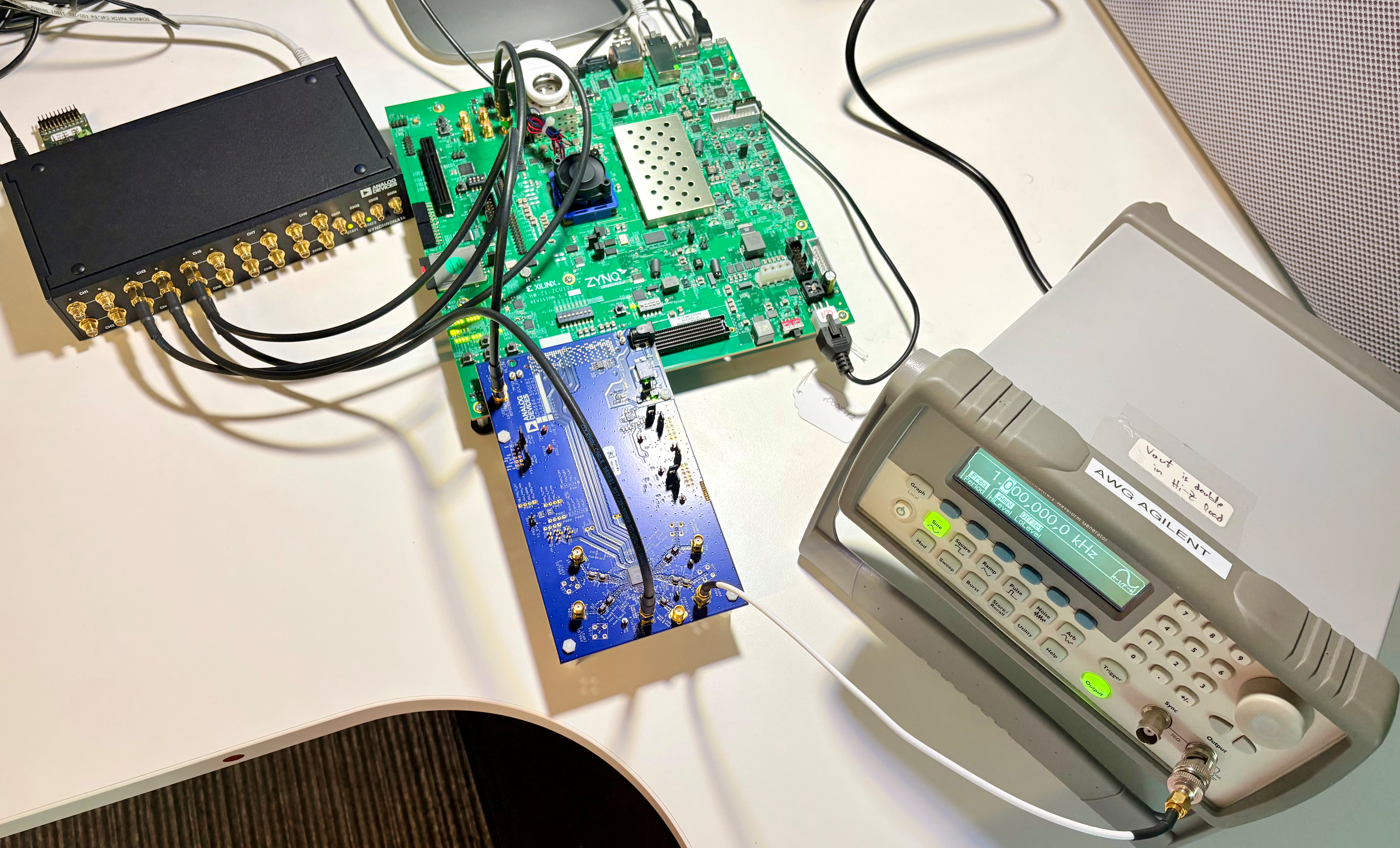
AD9694/ZCU102
Follow the steps in this order, to avoid damaging the components:
Note
The AD‑SYNCHRONA14‑EBZ module is optional. Users may use any alternative clock source as required by their setup.
Set up the AD-SYNCHRONA14-EBZ clock source:
The AD-SYNCHRONA14-EBZ provides all clocks required for this setup. Refer to the AD-SYNCHRONA14-EBZ for board setup and GUI installation instructions.
Once the Synchrona GUI is open (as described in the GUI section of that guide), configure the output channels as follows:
Enable channels 3, 5, and 6.
Set the output frequencies:
Channel
Frequency (Hz)
3
3906250
5
250000000
6
1000000000
Click Reload Config to apply the settings.
Connect the GPIO serial port of the AD-SYNCHRONA14-EBZ to the ZCU102 using the 20-pin ribbon cable, pin-to-pin (all 20 pins connected directly, 1-to-1).
Prepare the AD9694-500EBZ:
Configure the jumpers as described in the User guide hardware configuration section.
Connect channel 9 output of the AD-SYNCHRONA14-EBZ to J203 (500 MHz ADC sample clock, 50 Ohm coaxial cable).
Connect channel 10 output of the AD-SYNCHRONA14-EBZ to the ZCU102 reference clock input (250 MHz JESD204B reference clock).
Connect the signal source to J101 (Channel A) and/or J102 (Channel B), J104 (Channel C), J107 (Channel D) via an antialiasing filter.
Plug the AD9694-500EBZ into the FMC HPC1 connector on the ZCU102.
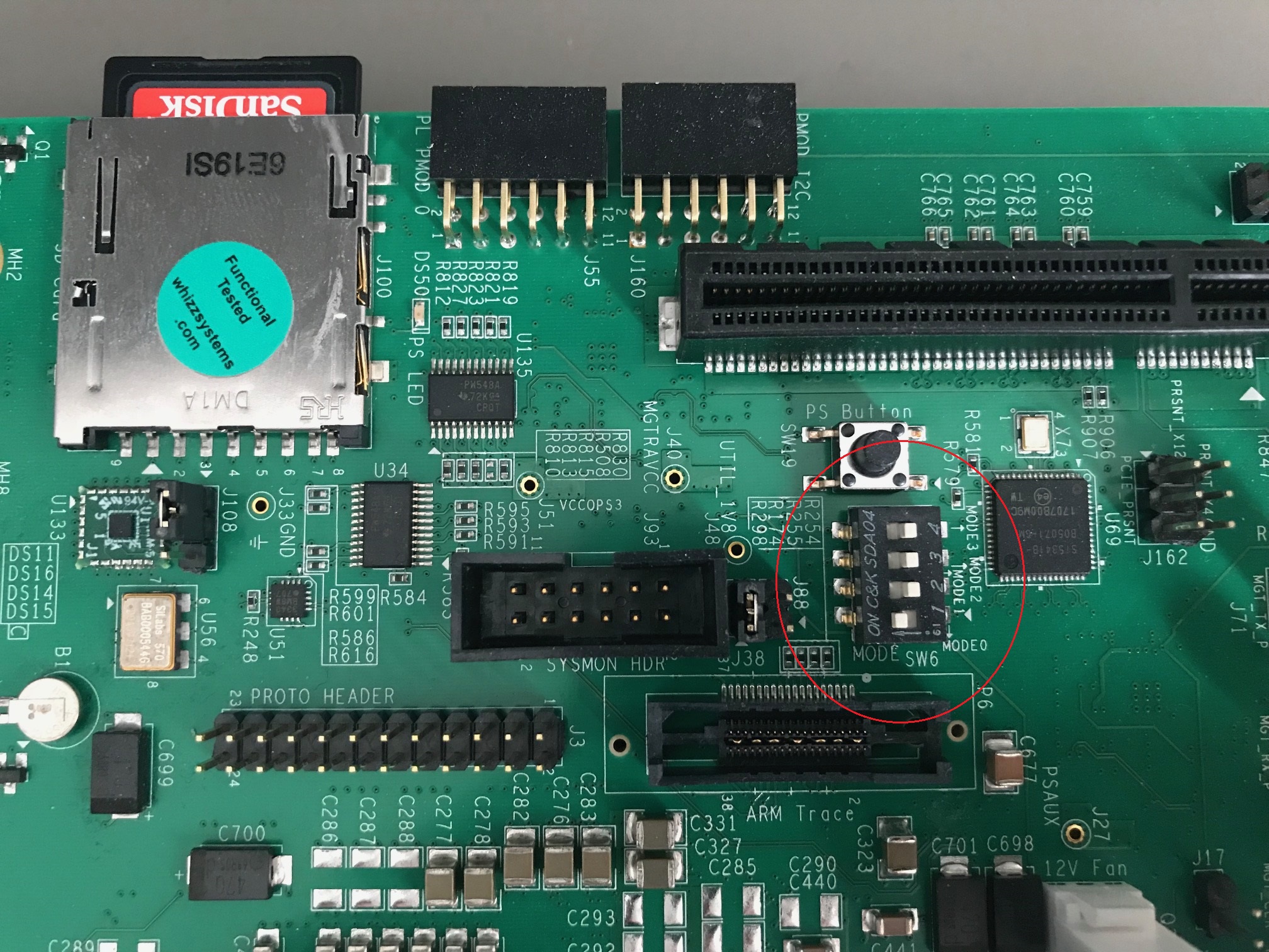
Insert the SD card into the SD card socket on the ZCU102.
Configure the ZCU102 for SD card boot mode (SW6[4:1] = OFF, OFF, OFF, ON):
Plug in an Ethernet cable from your router/switch to the Ethernet port on the FPGA board.
Connect USB UART J83 (Micro-USB) to your host PC.
(Optional) Connect a monitor via HDMI and a USB keyboard and mouse.
Connect the power supply to the ZCU102.
Turn on the power switch on the FPGA board.
Observe kernel and serial console output messages on your terminal (use the first ttyUSB or COM port registered, 115200 8N1).
Boot messages
The following is what is printed in the serial console after connecting to the correct ttyUSB or COM port:
.. TO BE ADDED
Useful commands for the serial terminal
Login information
user: analog password: analog
To find the IP address of the FPGA board:
~$
ifconfig
To see the IIO devices detected:
~$
iio_info | grep iio:device iio:device0: axi-ad9694-hpc (buffer capable)
iio:device1: xadc
To power off the system safely (wait for the final message, then flip the power switch):
~$
poweroff
To reboot:
~$
reboot
Important
This is a persistent file system. Do not cut power without shutting down
first — use poweroff or sudo shutdown -h now to avoid filesystem
corruption.
Using IIO Oscilloscope
After booting process is complete, you can open IIO-Oscilloscope. Learn more about it here. You can interact with the IIO-Osc GUI either directly or over the network.
Once the board is booted and you have the IP address:
Open IIO Oscilloscope on your host PC.
Connect to the ZCU102 by entering its IP address.
Select the AD9694 device from the device list.
Configure the capture settings (sample rate, decimation, DDC NCO frequency as needed).
Click Capture to view the ADC data in time domain or FFT.
Captured Loopback Signal Time Domain
Captured Loopback Signal Frequency Domain
For further details on IIO Oscilloscope features, refer to its IIO Oscilloscope documentation.