User Guide
Overview
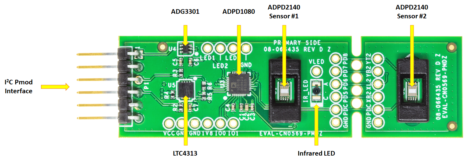
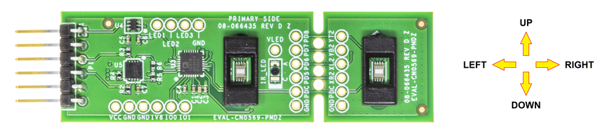
The EVAL-CN0569-PMDZ is a 4-layer printed circuit board (PCB) that allows evaluation of the CN-0569 Infrared Light Angle Sensor Module for Gesture Recognition. The board is fabricated with a 0.5 oz./1 oz. copper cladding (external layers overplated to 1.5 oz.) and IPC-4101 (or IPC-4103) laminates and bonding materials.
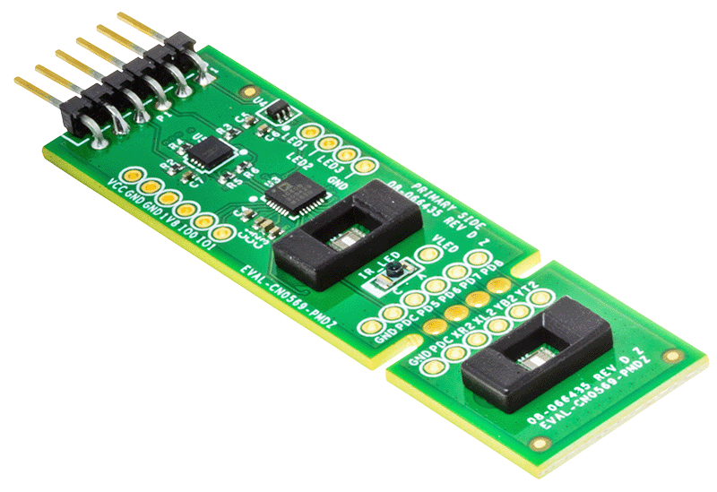
Designed to use the I²C Pmod hardware interface, the EVAL-CN0569-PMDZ features a small form-factor with PCB dimensions of 2.7 in (68.58 mm) × 0.8 in (20.32 mm) x 0.062 in (1.5748 mm). The evaluation board uses the standard 1 x 6, 0.1 in (2.54 mm) right-angle male header for I²C Pmod devices. Two 3D-printed optical baffles are included with the EVAL-CN0569-PMDZ for use with the onboard ADPD2140 sensors.
Evaluation Board Hardware
I²C Pmod Connector (P1)
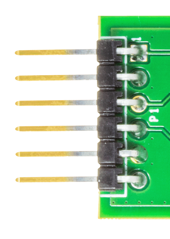
The controller board must be connected to the EVAL-CN0569-PMDZ through the 1 x 6, 0.1 in. (2.54 mm) right-angle header (P1). The pinout of this connector follows the standard I²C Pmod specification, as shown below:
I²C Pmod Connector (P1) Pinout
Pin Number |
Pin Name |
Pin Function on the EVAL-CN0569-PMDZ |
|---|---|---|
1 |
INT |
General-Purpose Input/Output 0. Actual function depends on the configuration of the ADPD1080 GPIO0 pin. |
2 |
RESET |
No connection. |
3 |
SCL |
I²C SCL. I²C Clock from the controller board to the ADPD1080. |
4 |
SDA |
I²C SDA. I²C Data from the controller board to the ADPD1080. |
5 |
GND |
Ground |
6 |
VCC |
Pmod VCC. Input power to the EVAL-CN0569-PMDZ. |
Note
Connecting Hardware Designed for Digilent I²C Pmod Interface Specification Ver. 1.0.0:
Version 1.0.0 of the Digilent Pmod Interface Specification required 2×4 headers to be used for I²C devices, instead of the 1x6 headers specified by later versions. The EVAL-CN0569-PMDZ can still be used with controller boards that follow this old standard (such as the EVAL-ADICUP3029). In this case however, the INT pin of the evaluation board will have to be manually wired if access to the ADPD1080 GPIO0 pin is needed by an application.
Test Points (Power, GPIO, and LED Driver Pins)
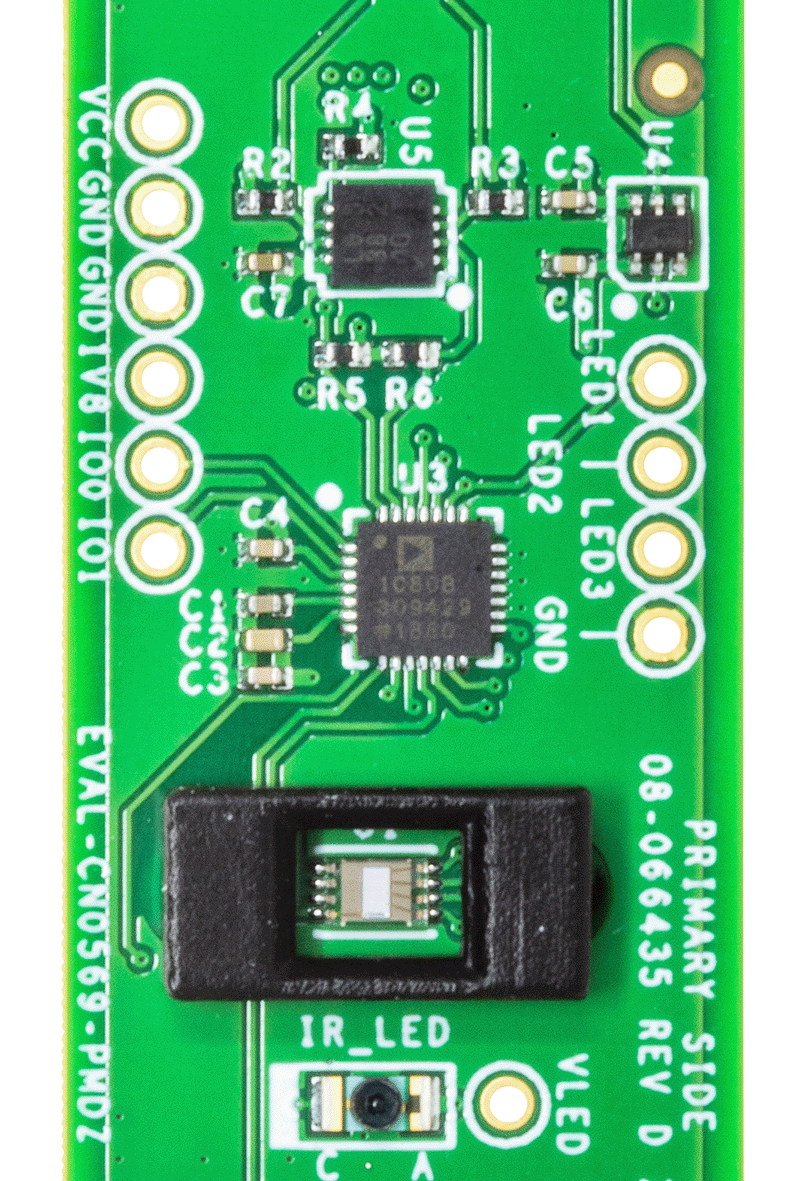
The EVAL-CN0569-PMDZ contains several test points that can be used to connect to the GPIO and LED driver pins of the ADPD1080 photometric front end device.
Test Point |
Hardware Pin |
Pin Function on the EVAL-CN0569-PMDZ |
|---|---|---|
IO0 |
ADPD1080 (U3) GPIO0 |
General Purpose Input/Output 0. Actual function depends on the configuration of the ADPD1080 GPIO0 pin. |
IO1 |
ADPD1080 (U3) GPIO1 |
General Purpose Input/Output 1. Actual function depends on the configuration of the ADPD1080 GPIO1 pin. |
LED1 |
ADPD1080 (U3) LEDX1 |
LED 1 Driver Current Sink. Used by the onboard infrared LED by default. |
LED2 |
ADPD1080 (U3) LEDX2 |
LED 2 Driver Current Sink. Unused by default. Can be connected to an external LED. |
LED3 |
ADPD1080 (U3) LEDX3 |
LED 3 Driver Current Sink. Unused by default. Can be connected to an external LED. |
1V8 |
ADPD1080 (U3) AVDD/DVDD |
1.8 V Supply. Regulated 1.8 V used to power the ADPD1080. |
VCC |
Pmod VCC |
Pmod VCC. Input power to the EVAL-CN0569-PMDZ. |
VLED |
LED Supply |
Supply Voltage for IR_LED. Shorted to Pmod VCC by default. |
GND |
GND |
Ground |
The actual functions of the GPIO0 and GPIO1 pins can be set via the registers. For details on the the functions of these pins, please refer to the ADPD1080 datasheet.
Note
IO0 and IO1 are connected directly to the pins of the ADPD1080. Level shifting is needed to interface with these test points if the external circuit does not support 1.8 V logic. GPIO0 is also available via the INT pin of the I²C Pmod connector (P1). When accessed from this pin, the GPIO signal will use the Pmod VCC as its logic level (same as the I²C signals).
If needed by the application, the three LED drivers of the ADPD1080 can be used with external LEDs. To do this, connect the cathode pin of the external LED to any of the LED1, LED2 and LED3 test points. The anode pin of the external LED should be connected to a supply voltage.
Note that LED1 is normally used by the infrared LED (IR_LED) of the EVAL-CN0569-PMDZ. To use this with an external LED instead, the zero Ohm resistor (R1) must be removed first.
Warning
For proper operation with an external LED, the voltage level on the corresponding LED driver test point must not exceed 3.6 V.
Test Points (Photodiode Inputs)
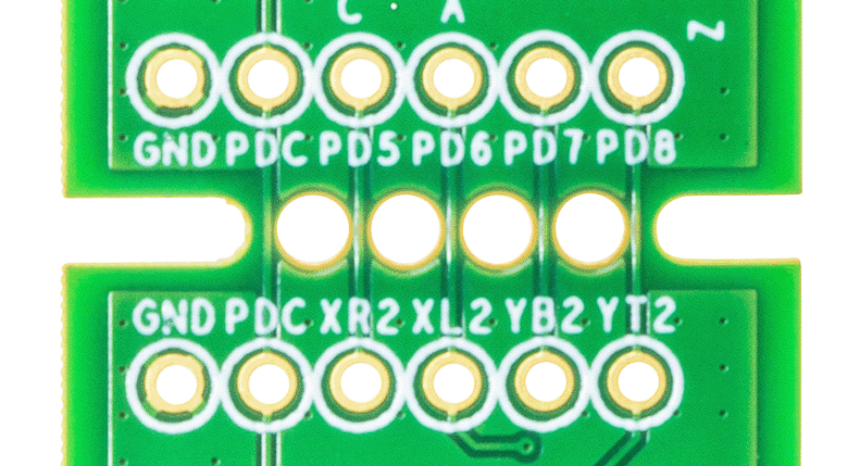
The EVAL-CN0569-PMDZ uses two ADPD2140 sensors spaced 1 in (25.4 mm) apart to implement the gesture sensing algorithm. However, it is possible to modify this distance using by splitting the board into two along the breakaway line and manually wiring the corresponding test points together. Two rows of test points are provided for this application.
Test Point |
Hardware Pin |
Pin Function on the EVAL-CN0569-PMDZ |
Hardware Pin |
Test Point |
|---|---|---|---|---|
PD5 |
ADPD1080 (U3) PD5 |
Photodiode Current Input (Anode) 5 |
ADPD2140 (U2) XR |
XR2 |
PD6 |
ADPD1080 (U3) PD6 |
Photodiode Current Input (Anode) 6 |
ADPD2140 (U2) XL |
XL2 |
PD7 |
ADPD1080 (U3) PD7 |
Photodiode Current Input (Anode) 7 |
ADPD2140 (U2) YB |
YB2 |
PD8 |
ADPD1080 (U3) PD8 |
Photodiode Current Input (Anode) 8 |
ADPD2140 (U2) YT |
YT2 |
PDC |
ADPD1080 (U3) PDC |
Photodiode Common Cathode Bias |
ADPD2140 (U2) PDC |
PDC |
GND |
GND |
Ground |
GND |
GND |
Gesture Sensing Reference Demo and Software
A basic gesture sensing example application for the EVAL-CN0569-PMDZ was developed using the EVAL-ADICUP3029 platform.
Note
For more information on this demo, please refer to the Optical Gesture Sensor Demo page.
Schematic, PCB Layout, Bill of Materials
Download
EVAL-CN0569-PMDZ Design & Integration Files
Schematic
Bill of Materials
Gerber Files
Assembly Drawing
Registration
Tip
Receive software update notifications, documentation updates, view the latest videos, and more when you register your hardware. Register to receive all these great benefits and more!