User guide
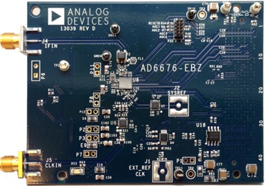
Hardware guide
Power supply
The power supply comes from the FMC connector, given by the FPGA carrier board. The EVAL-AD6676 evaluation board uses an on-board LDO regulator powered through the FMC interface to generate the required 1.1V and 2.5V supply domains for the AD6676.
The board requires VADJ set to 2.5V. The VADJ configuration can be found in the README.md file at: projects/ad6676evb/zc706.
Clock configuration
Clock source selection
On the FMC card, choose between the available CLKIN sources:
On-board 200 MHz XO (default) — R95 and R100 installed
External clock via J5 — remove R95 and R100
The ADC clock frequency (FADC) operates between 2.0 GHz to 3.2 GHz when using an external synthesizer, or 2.925 GHz to 3.2 GHz when using the internal synthesizer.
Clock routing options
On the FMC card, choose between the available clock routing options:
PECL comparator (default) — C35, C47, C48 installed (C38, C45, C46 uninstalled); CLKIN is routed through a PECL-output comparator that drives the AD6676 clock inputs.
Direct RF via ceramic balun — install C38, C45, C46 and remove C35, C47, C48.
JESD204B reference and device clocks
The JESD204B interface operates with the following clock relationships:
Lane rate: 4 Gbps
Reference clock: 200 MHz (lane rate / 20)
Device clock: 100 MHz (lane rate / 40)
ADC clock (FADC): 3200 MHz
RF and data interfaces
The AD6676 is a highly integrated IF subsystem that can digitize radio frequency (RF) bands up to 160 MHz in width centered on an intermediate frequency (IF) of 70 MHz to 450 MHz.
High instantaneous dynamic range
Noise figure (NF) as low as 13 dB
Noise spectral density (NSD) as low as −159 dBFS/Hz
IIP3 up to 36 dBm with spurious tones <−97 dBFS
Tunable band-pass Σ-Δ analog-to-digital converter (ADC)
70 MHz to 450 MHz IF center frequency
2.0 GSPS to 3.2 GSPS ADC clock rate
16-bit I/Q rate up to 266 MSPS
On-chip digital signal processing
NCO and quadrature digital downconverter (QDDC)
Selectable decimation factor of 12, 16, 24, and 32
Automatic gain control (AGC) support
On-chip attenuator with 27 dB span in 1 dB steps
Data interface: Single or dual lane JESD204B, subclass 1
M=2 converters, S=1 sample per frame, NP=16 bits
L=2 lanes: F=2 octets per frame
L=1 lane: F=4 octets per frame
8B10B encoding
Control interface: SPI interface for setup and control
Analog input
Connect the IF signal to the SMA connector on the evaluation board. The AD6676 contains a 50 Ω input attenuator programmable in 1 dB steps with a range from 0 to −27 dB.
IBIS models
AD6676 IBIS AMI Model — email highspeed.converters@analog.com to request
Software guide
The EVAL-AD6676 evaluation board is supported with the libiio library. This library is cross-platform (Windows, Linux, Mac) with language bindings for C, C#, Python, MATLAB, and others.
ADI IIO Oscilloscope
The IIO Oscilloscope is a cross-platform application for interfacing with IIO devices, enabling you to configure device parameters and visualize data.
Important
Make sure to download/update to the latest version of IIO Oscilloscope.
For Linux
Remote run on host
The IIO Oscilloscope application can be used to connect to another platform that has a connected device, to configure the device and read data from it. This application is not for performance testing, but rather showcasing the basic features.
Please see IIO Oscilloscope documentation for installation steps and more details.
Build and start osc on a network-enabled Linux host.
For Windows computers, open the application from the start menu.
Once the application is launched, go to Settings > Connect > URI and type “ip:” then the IP address of the target in the pop-up window. This IP can be found out with a command from the previous section of this documentation.
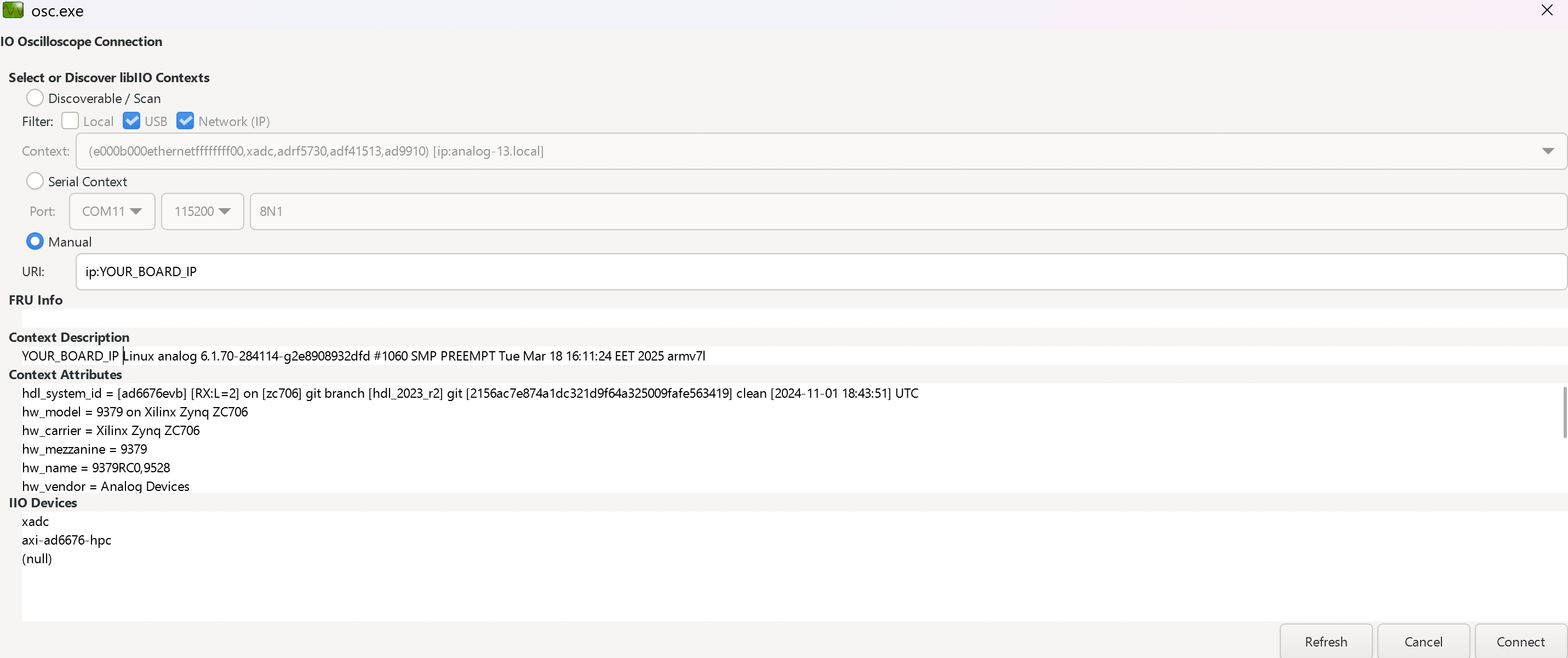
Locally run on the board
If you connected an HDMI monitor to your FPGA and a mouse and a keyboard (both on one dongle), you can navigate the ADI Kuiper Linux that is on the FPGA.
Going to the top left corner icon (the menu icon), search for IIO Oscilloscope. Opening it will automatically connect to the setup and you can use the application.
For no-OS
For connecting IIO Oscilloscope to no-OS applications, they need to be built with the IIOD=y flag. This way, the no-OS applications will run an IIO daemon that is awaiting connections from the IIO Oscilloscope.
As indicated in the boot log, the board runs an IIOD server over the serial (UART) connection.
Disconnect or close the serial terminal used to view the boot log.
Once done with the installation or an update of the latest IIO Oscilloscope, open the application.
Select the Serial backend and configure the connection with the settings shown at the end of the boot log.
Press Refresh to display the available IIO devices and press Connect.
Note
The serial port is the COM port on Windows or /dev/ttyUSBx on Linux.
Data capture
Note
Device names and channel definition may differ between no-OS and Linux.
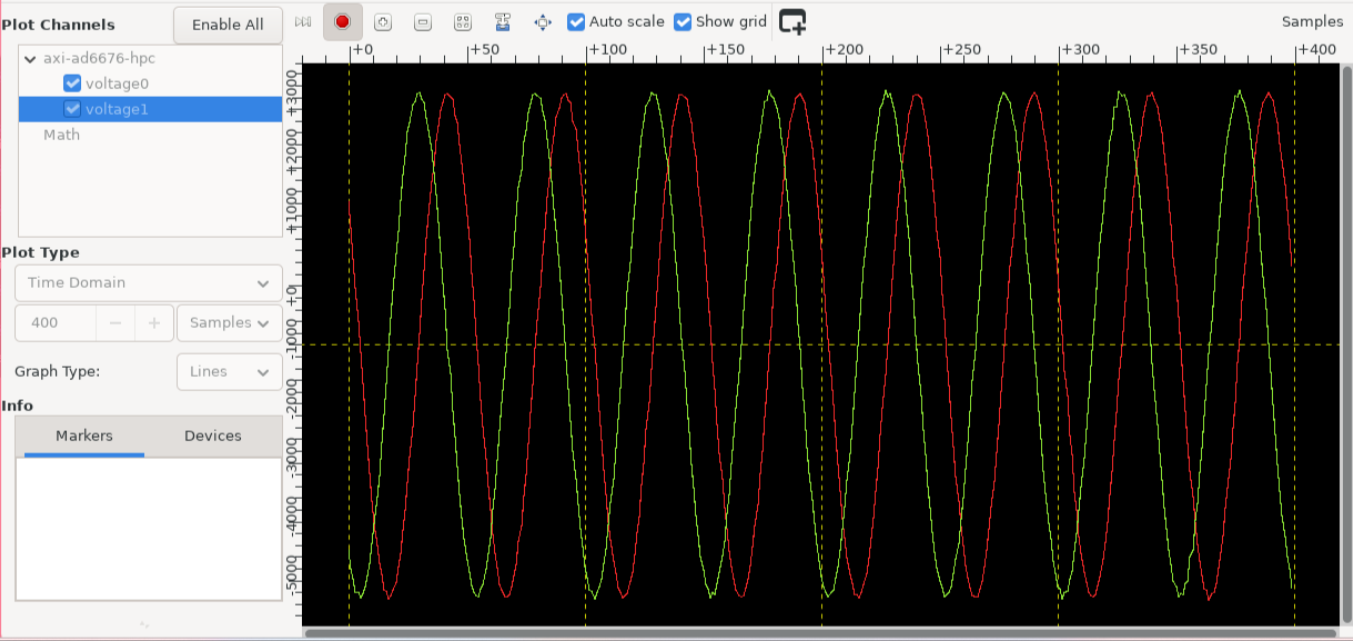
Time domain:
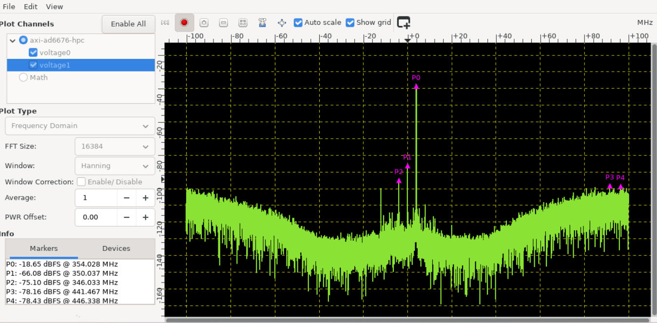
Frequency domain:
Scopy
Scopy is a cross-platform software toolbox for interfacing with ADI devices, enabling you to configure device parameters, visualize data, and perform advanced signal analysis.
PyADI-IIO
PyADI-IIO is a Python abstraction module for ADI hardware with IIO drivers. An AD6676 example can be found here.
Linux driver
See also
No-OS
See also