SDP-H1 quick start
This user guide describes both the hardware and software setup needed to acquire data capture from EVAL-AD9740, EVAL-AD9742, EVAL-AD9744 or EVAL-AD9748 evaluation boards to characterize the AD9748 8-bit, AD9740 10-bit, AD9742 12-bit, and AD9744 14-bit, 210 MSPS TxDAC digital-to-analog converters.
The evaluation boards have an FMC form-factor with FMC connector that is compatible to the Vita 57.1 standard. The boards provide provision for on-board clocking (using ACE software for control) or external direct clocking. The EVAL-SDP-H1 controller board automatically formats the data and sends it to the evaluation board, which simplifies the evaluation of the device. The evaluation board receives power from the SDP-H1 power supply.
This guide shows how AD9740-FMC-EBZ, AD9742-FMC-EBZ, AD9744-FMC-EBZ or AD9748-FMC-EBZ work with SDP-H1 controller board developed by Analog Devices. Link to the previous user guide document is provided for customers who still have the DPG2 controller board.
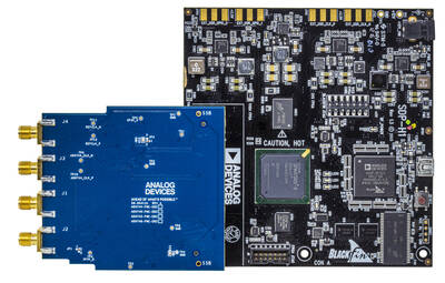
Reconfiguring the Evaluation Board
This section details the quick start procedures for setting up the EVAL-AD9740, EVAL-AD9742, EVAL-AD9744 or EVAL-AD9748 evaluation board. Refer to the table below to configure the clock and output option of the evaluation board.
Clock Configuration
The evaluation board has a provision for on-board or external clocking configuration.
Steps
On-board (ADF4351)
External Clock (J3 and J4)
Install (0-ohm, 0402)
R46, R47, R50, R51
R42, R44, R45, R48, R49
Don’t Install
R44, R45, R48, R49
R43, R46, R47, R50, R51
The on-board clocking configuration is implemented by default.
For external clocking configuration, split the output of a High-Frequency Clock Source (e.g. SMA100A) using an SMA T-adapter and connect to J3 and J4 of the evaluation board. Set SMA to desired clock frequency and 16dBm output.
Output Configuration
The evaluation board has a provision for single-ended or differential output. The single-ended configuration is implemented by default.
Steps
Single Ended Output (J1 Only)
Differential Output (J1 and J2)
Install
T1 (ADT1-1+)
R19, R20 (0-ohm)
Don’t Install
R19, R20 (0-ohm)
T1 (ADT1-1+)
Board Jumpers Configuration
A 0402, 0-ohm resistor are installed on the jumpers. Move these 0-ohm resistors accordingly to the required configuration as shown below.
Name
Function
Options
JP1
DAC input data mode.
1 for twos complement, 3 for straight binary (default)
JP2
Clock input mode
1 for differential receiver, 3 for single-ended receiver, Float for PECL receiver (default)
JP3
ADF4351 RF Power Down
1 for power up (default), 2 for power down
Software Installation
The ACE software and DPGDownloader Lite are needed to configure the device. ACE is the software that is used to load the registers in the ADF4351 while DPGDownloader Lite is used to load the vector into the evaluation board. Install ACE from ace (Analysis | Control | Evaluation (ACE) Software). During installation, expand the High-Speed DAC Components list and select the DPG Lite and HSDAC eval boards support through SDP drivers checkboxes. The plugins for this board can be downloaded from the plugin manager in the ACE software.
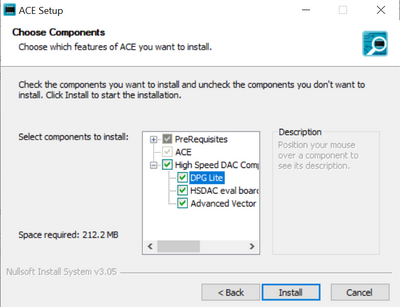
Configuring the EVB using ACE
To configure the evaluation board to output a 5.0MHz sine wave at 210MSPS with DPGDownloader Lite and ACE software, take the following steps:
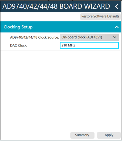
Follow the steps to set-up and configure the clocking of the eval board.
From the initial ACE screen, click the AD9744-FMC-EBZ.
On the Clocking Setup Tab, select Onboard clock (ADF4351) on the clock source drop-down menu, and enter 210MHz on the DAC clock field.
Click Apply and a summary window will pop up. Confirm if the entered details are correct.
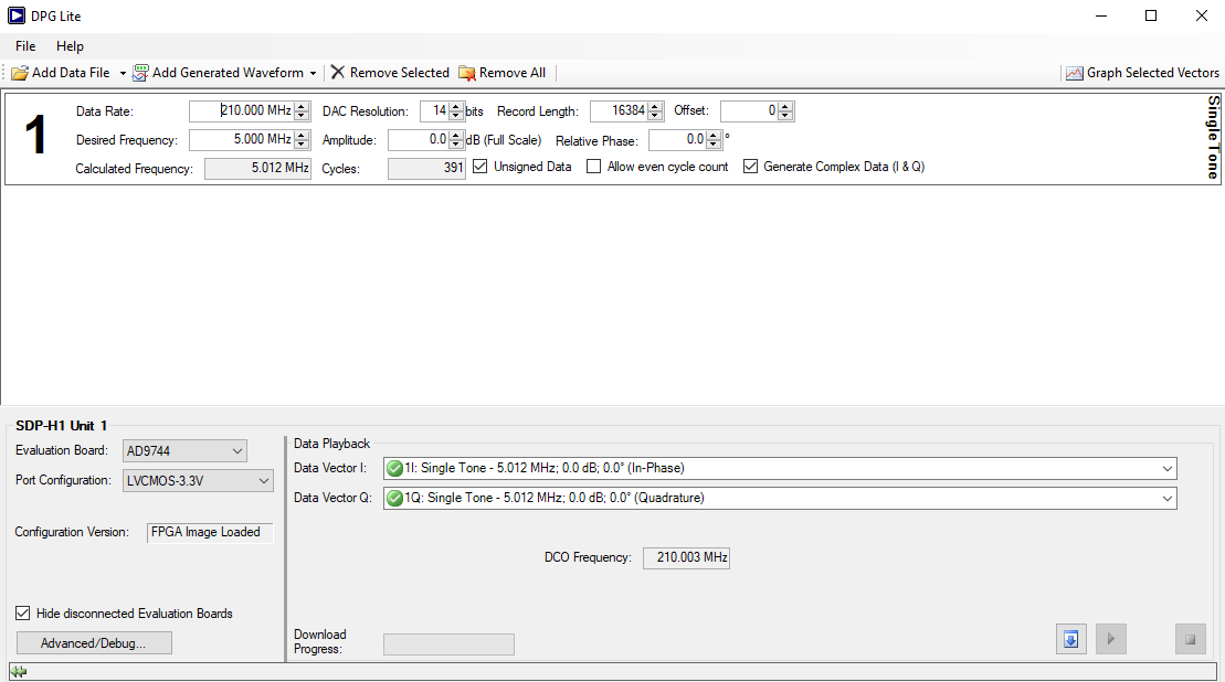
Loading a vector using DPGDownloader Lite
Follow the steps to generate and download a vector into the eval board.
Confirm first if the DCO frequency detected is the same as the clock frequency set on ACE (210MHz). Repeat the ACE process if frequencies don’t match.
In the DPGDownloader Lite window, click the Add Generated Waveform dropdown menu and select Single Tone as the vector type.
Refer to the table below for the appropriate frequency values and default settings.
Note
Select 14 bits DAC Resolution for all generics (AD9744, AD9740, AD9742 & AD9748). The NC pins are disconnected in the corresponding evaluation board.
FMC Pin
AD9744
AD9742
AD9740
AD9748
G9(MSB)
DB13
DB11
DB09
DB07
G10
DB12
DB10
DB08
DB06
H10
DB11
DB09
DB07
DB05
C10
DB10
DB08
DB06
DB04
H11
DB09
DB07
DB05
DB03
D11
DB08
DB06
DB04
DB02
G12
DB07
DB05
DB03
DB01
H13
DB06
DB04
DB02
DB00
G13
DB05
DB03
DB01
NC
H14
DB04
DB02
DB00
NC
C11
DB03
DB01
NC
NC
D12
DB02
DB00
NC
NC
D14
DB01
NC
NC
NC
D15
DB00
NC
NC
NC
In the Data Playback panel, select the 1I: Single Tone - 5.01 MHz; 0.0 dB; 0.0° (In-Phase) option from the I Data Vector dropdown menu.
Select the 1Q: Single Tone - 5.01 MHz; 0.0 dB; 0.0° (Quadrature) option from the Q Data Vector dropdown menu.
Click the Download button in the lower right of the Data Playback panel.
Click the Play button, located to the left of the Download button, to begin vector playback.
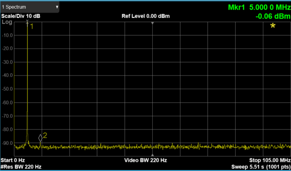
The signal frequency output then appears on the spectrum analyzer.
Verification
Output window that appears on the Spectrum Analyzer hardware. Ensure that the following options are set:
Connect Spectrum Analyzer to SMA J1.
Set the Stop frequency to 105.0MHz.
Set the Ref level to 0 dBm.
Set the Res BW to 220 Hz.
Set the VBW to 220 Hz.
Check that the DAC output, the top right Mrkr1, is approximately 5.0000 MHz and check that the amplitude is approximately 0 dBm.
Troubleshooting
On-Board LEDs
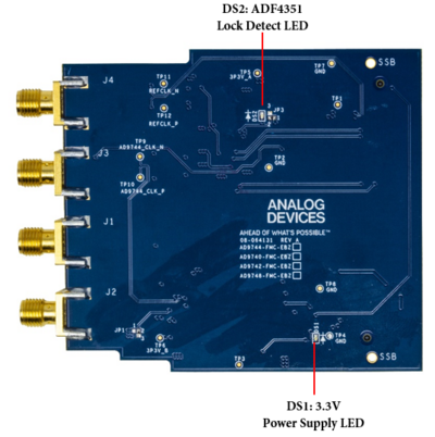
There are two LEDs on the evaluation board, which are the 3.3V power supply LED, and the ADF4351 lock detect LED. These LEDs are shown in Figure 6. These two LEDs will light up when 3.3V is supplied to the board, and when the ADF4351 clock chip is working properly.
DPGDownloader Lite Does Not Recognize the Evaluation Board
There may be cases where the DPGDownloader Lite does not recognize the evaluation board. If this occurs, open the DPGDownloader Lite and unplug then replug the USB cable. If DPGDownloader Lite still does not recognize the evaluation board, there is a chance that the firmware of the board is not updated and the evaluation board must be reprogrammed with the new firmware. Contact a local Analog Devices salesperson or distributor to arrange for this reprogramming to be done.
ACE Does Not Recognize the Evaluation Board
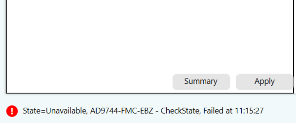
There may be cases where the AD9744 icon does not appear on the Attached Hardware tab of ACE, or the icon is there but once clicked, will indicate an Unavailable status on the bottom as shown in Figure 7. These errors can occur if the ACE software is started before powering up and connecting the evaluation board to the PC, or if the evaluation board is power cycled and ACE is not restarted. The most basic remedy for this issue is to close ACE and reopen it (restart). As long as the evaluation board is powered up and connected to the PC, ACE recognizes the evaluation board and will work again.
DCO Frequency is not correct or not detected
Check if the proper resistors are installed. If using the Onboard clock, check if DS2 LED lights up. If not, restart ACE and then reprogram the board with the desired clock frequency. If using an external clock source, increase the output power level to 20dBm. Make sure the resistors installed are properly soldered.
DAC Output Frequency is not correct
Check if the DCO Frequency detected on the DPG Panel matches the Data Rate field. These two should match for proper vector generation and playing to the DAC.