README
adrd2121_imu
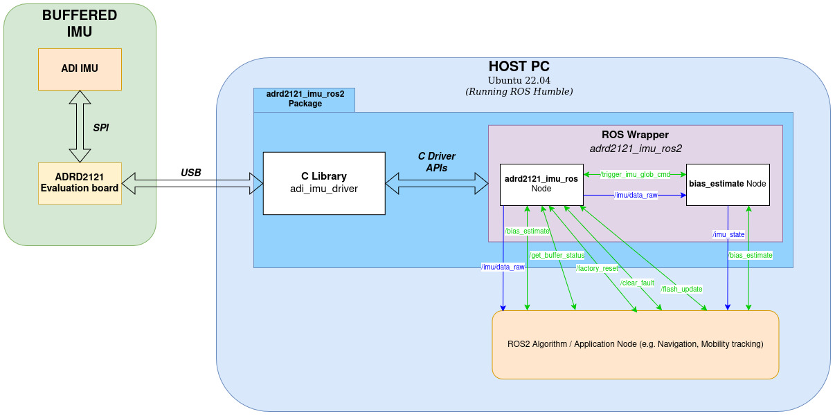
Background
This ROS2 package is an implementation of the prior ROS1 driver, now adapted for ROS2.
The ADRD2121 is a hardware and software solution designed to buffer IMU data. (For more info, see: EVAL-ADRD2121-EBZ Evaluation board)
A C-based library is used as a dependency: adi_imu_driver Github
Enable user to recover board either automatically or manually through functions and services.
Supported communication interface for Host <-> ADRD2121 are: USB.
Supported platform/s are: x86
Supported ROS2 Distro: Humble
Software Architecture
Software Setup
Clone this repository
Clone this package and its submodules into your workspace:
cd ~/ros2_ws/src
git clone <copied SSH or HTTPS link here> adrd2121_imu
Install Dependencies
List of dependencies:
IMPORTANT: Dependencies will automatically be cloned and installed during build. Proceed to Build.
Build
If not familiar with building a ROS2 package, you may visit here.
Here is how to activate TIMING_DEBUG when building the package:
Build at ~/ros2_ws
####### [TERMINAL 1] #######
# Make sure that ROS2 environment variables are properly sourced
## $ source/opt/ros/<ROS2 version>/setup.bash
$ source /opt/ros/humble/setup.bash

# Resolve any dependencies
$cd ~/ros2_ws
$ rosdep install -i --from-path src --rosdistro humble -y

# Build
$ colcon build

## To clean first before building, you may run the following instead:
## $ colcon build --cmake-clean-first

## To enable the Timing Debug mode, you may run this:
## $ colcon build --cmake-args -DADRD2121_IMU_TIMING_DEBUG=ON
Note: Building will automatically add a dependencies subdirectory and should be ignored by git.
Note: Sourcing should also be done in another terminal as launching should not be done in the same terminal where the package has been built, as discussed here in ROS2 Source the overlay.
IMPORTANT
When changing workspaces (commit_ws <-> test_ws), also make sure that a new terminal is used, as there will be times that the package from one workspace will be the one to be built even after changing workspaces.
Hardware Setup
Access to device
When the device is connected to the Host PC, it will be listed like
/dev/ttyACM0where number can change depending on how many ACM devices are connected.To access the device, listed below are two ways to so. IMPORTANT: This is required before Launch, else launch will fail.
Temporary Access
This method would be required every time the device was connected to the Host PC.
Step 1. Before connecting run the following command in the terminal dmesg -w
Sample Result:
[ 1343.478484] usb 1-5: new full-speed USB device number 9 using xhci_hcd
[ 1343.628368] usb 1-5: New USB device found, idVendor=0483, idProduct=5740, bcdDevice= 2.00
[ 1343.628372] usb 1-5: New USB device strings: Mfr=1, Product=2, SerialNumber=3
[ 1343.628374] usb 1-5: Product: STM32 Virtual ComPort
[ 1343.628376] usb 1-5: Manufacturer: STMicroelectronics
[ 1343.628377] usb 1-5: SerialNumber: 3984356B3037
[ 1343.650144] cdc_acm 1-5:1.0: ttyACM0: USB ACM device
[ 1343.655026] usbcore: registered new interface driver cdc_acm
[ 1343.655028] cdc_acm: USB Abstract Control Model driver for USB modems and ISDN adapters
In this result, the device was listed as /dev/ttyACM0.
Step 2. Change the permission of the device such that the owner, group, and others have rw access to it.
$ sudo chmod 666 /dev/ttyACM0
Step 3. Check if successful:
$ ls -l /dev/ttyACM0
crw-rw-rw- 1 root dialout 166, 0 Feb 28 11:37 /dev/ttyACM0
Permanent Access (via custom udev rules)
This method would only be required on initial setup, but may vary on each device (e.g. if you have more than 1 ADRD2121 + IMU device, you need to create a udev rule for each one).
Step 1. Before connecting run the following command in the terminal dmesg -w
Sample Result:
[ 1343.478484] usb 1-5: new full-speed USB device number 9 using xhci_hcd
[ 1343.628368] usb 1-5: New USB device found, idVendor=0483, idProduct=5740, bcdDevice= 2.00
[ 1343.628372] usb 1-5: New USB device strings: Mfr=1, Product=2, SerialNumber=3
[ 1343.628374] usb 1-5: Product: STM32 Virtual ComPort
[ 1343.628376] usb 1-5: Manufacturer: STMicroelectronics
[ 1343.628377] usb 1-5: SerialNumber: 3984356B3037
[ 1343.650144] cdc_acm 1-5:1.0: ttyACM0: USB ACM device
[ 1343.655026] usbcore: registered new interface driver cdc_acm
[ 1343.655028] cdc_acm: USB Abstract Control Model driver for USB modems and ISDN adapters
In this result, the device subsystem=tty, idProduct=5740, idVendor=0483, and SerialNumber: 3984356B3037.
Note: The idProduct and idVendor of the device will be the same and only the SerialNumber will change.
In case, the SerialNumber did not appear in Step 1, try the following command:
# $ sudo lsusb -d <idVendor:idProduct> -v | grep iSerial
$ sudo lsusb -d 0483:5740 -v | grep iSerial
  iSerial                 3 3984356B3037
Step 2. Install the following packages.
$ sudo apt-get install usbutils
$ sudo apt-get install udev
Step 3. Create the udev rule file:
File Name: 99-adrd2121.rules
99 is the order of the rule, the lower number will be read first.
adrd2121 can be changed depending on your preference.
99-adrd2121.rules file content:
SUBSYSTEM=="tty", ATTRS{idVendor}=="0483", ATTRS{idProduct}=="5740", ATTRS{serial}=="3984356B3037", SYMLINK+="adrd2121", MODE="0666"
IMPORTANT
The
SYMLINK+="adrd2121"will create a symbolink link/dev/adrd2121for the specific device that matches the SUBSYSTEM, idVendor, idProduct, and serial number.This would mean that you can also access the device via the device name
/dev/ttyACM0(depending on the logs in Step 1) or/dev/adrd2121.Adding the
SYMLINK+="adrd2121"resolves any problem to changing devices names.
Step 4. Copy 99-adrd2121.rules to /etc/udev/rules.d
$ sudo cp 99-adrd2121.rules /etc/udev/rules.d
Step 5. Restart USB device Manager
$ sudo udevadm control --reload-rules && sudo udevadm trigger
# Wait at least 5 seconds for restart to finish
Step 6. Check if successful:
$ ls -l /dev/ttyACM0
crw-rw-rw- 1 root root 166, 0 Feb 28 11:39 /dev/ttyACM0
$ ls -l /dev/adrd2121
lrwxrwxrwx 1 root root 7 Feb 28 11:38 /dev/adrd2121 -> ttyACM0
Launch
This section will discuss how to use the launch files, and Launch files will run adrd2121_imu_node and (optionally) bias_estimate_node_ros2 in sequence depending on the TimerAction delay.
The included launch files will run the following nodes:
For ADIS16470
For ADIS16500
Default launch
###### [TERMINAL 2] ######
#Properly sourcing the overlay
$ cd ~/ros2_ws
$ source install/setup.bash

# Launch
## $ ros2 launch adrd2121_imu <imu_product>.launch.py
## Example for launching ADIS16470
$ ros2 launch adrd2121_imu adis16470.launch.py
IMPORTANT
Make sure that a separate terminal is used other than the terminal used to build the package, as mentioned here.
Change log level for nodes
## If the user wants to enable debug logs, launch the package with the following command:
$ ros2 launch adrd2121_imu adis16470.launch.py log_level:=DEBUG

## Other available log levels are as follows: INFO (default), WARN, ERROR
Delayed execution of bias_estimate_node
Another thing to take note is the delayed launching of the bias_estimate node, shown below:
...
OnProcessStart(
                target_action=main_node_run,
                on_start=[
                    TimerAction(
                        period=5.0,
                        actions=[bias_node_run]
                    )
                ]
            )
...
This implementation launches the main node (adrd2121_imu_node) first, then in the background starts a timer (period), running in seconds. Once the timer finishes, only then the action (bias_node_run) will be executed.
The user is freely to change the period value if so desired. This clause was added in order to avoid sync issues with bias_estimate node going to timeout after not detecting the /imu/data_raw topic.
Nodes
adrd2121_imu_node
Operation modes
The user will be able to configure what mode to run through the mode_of_operation parameter.
Board recovery
To set the board recovery during initialization, set the parameter enable_init_recover to true.
If enabled, the node will automatically check the status of the board and recover to working state if applicable.
Published topics
/imu/data_raw (default:
sensor_msgs/Imuor custom msg:adrd2121_imu/AdiImu)Raw IMU data containing angular velocity (x,y,z) and linear_acceleration (x,y,z)
See AdiImu.msg for more info on custom message.
Msg type is set in adi_imu_driver_node Parameters.
Advertised services
/trigger_imu_glob_cmd (adrd2121_imu/ImuGlobCmd)
Write 1 to specified BIT in GLOB_CMD IMU Register;
See custom service message: srv/ImuGlobCmd.srv
NOT SUPPORTED in ADIS16500
NOTE:
Only the Bias Correction Update (Bit 0) is supported for now;
DO NOT directly call this service as it will affect the IMU’s performance;
For Bias Correction Update, IMU needs to be standstill for at least 40s or else, the IMU data would gain offset. See /bias_estimate service instead.
/factory_reset (std_srvs/Trigger)
This will revert the ADRD2121 back to its factory configuration
/clear_fault (std_srvs/Trigger)
This should remove all the FAULT status in the ADRD2121
/flash_update (std_srvs/Trigger)
This will save the current configuration of the Buffer Board to the flash memory, which will be loaded in the next boot-up.
/get_buffer_status (adrd2121_imu/BufStatus)
This is meant for acquiring the current status of the Buffer Board.
Status codes and their implications can be found in the ADRD2121 Github’s register definitions (see STATUS).
Parameters
IMPORTANT:
If any of these parameters are not set, the default values will be used. See config/[IMU_name].yaml on how these parameters are set.
There will be times that some parameters will not be declared if it will not be used in the whole runtime i.e. if update_imu_accl_bias is false, imu_accl_bias will not be declared.
Changing the value of a parameter during runtime (via
ros2 param set) is not possible as parameters are set to read-only.
ROS Specific Parameters
topic_name (string, default: imu/data_raw)
IMU topic name
frame_name (string, default: imu)
IMU frame name
msg_type (int, default: 1)
Message type of topic
“1” : sensor_msgs/Imu
“2” : adrd2121_imu/AdiImu
mode_of_operation (int, default: 0)
This is used to check what operation mode the node will run in.
“1” : STREAM - this will enable all functions related to data streaming.
Services available: trigger_imu_glob_cmd and get_buffer_status
“2” : RECOVERY - data streaming is disabled here. This is meant for clearing error codes.
Services available: factory_reset, clear_fault, flash_update, and get_buffer_status
This will skip any initializations for both IMU and the Buffer Board, but UART communication must be established.
Communication Interface Parameters
usb_dev (string, default: /dev/ttyACM0)
Device name
usb_baud (int, default: 921600)
USB Baud Rate
ADRD2121 Parameters
buf_burst_count (int, default: 1)
Burst Count is a parameter that allows multiple transactions in a single syscall
enable_imu_burst (bool, default: true)
Enables IMU burst data capture for buffer entries (IMU <-> ADRD2121)
See BUF_CONFIG Register
buf_overflow (int, default: 0)
Buffer overflow behavior;
“0” : Stop Sampling
“1” : Replace Oldest Data
See BUF_CONFIG Register
enable_buf_pps (bool, default: false)
Trigger PPS_ENABLE
See USER_CMD Register
buf_data_rdy_sel (int, default: 1)
Select which IMU DIO output pin is treated as data ready
“1” : BUF_DIO1
“2” : BUF_DIO2
“4” : BUF_DIO3
“8” : BUF_DIO4
See DIO_INPUT_CONFIG Register
For ADIS16470 and ADIS16500, only BUF_DIO1 is possible.
buf_data_rdy_pol (int, default: 1)
Data ready trigger polarity
“0” : triggers on falling edge
“1” : triggers on rising edge
buf_pps_sel (int, default: 0)
Select which host processor DIO output pin acts as a Pulse Per Second (PPS) input
“0” : Disabled
“1” : BUF_DIO1
“2” : BUF_DIO2
“4” : BUF_DIO3
“8” : BUF_DIO4
See DIO_INPUT_CONFIG Register
buf_pps_pol (int, default: 1)
PPS trigger polarity
“0” : triggers on falling edge
“1” : triggers on rising edge
See DIO_INPUT_CONFIG Register
buf_pps_freq(int, default: 0)
Possible values: [0-3], where PPS Input Frequency is (10 ^ (buf_pps_freq) Hz).
See DIO_INPUT_CONFIG Register
buf_pin_pass (int, default: 0)
Select which pins are directly connected from the host processor to the IMU using an ADG1611 analog switch
“0” : Disabled
“1” : BUF_DIO1
“2” : BUF_DIO2
“4” : BUF_DIO3
“8” : BUF_DIO4
See DIO_OUTPUT_CONFIG Register
buf_watermark_int (int, default: 0)
Select which pins are driven with the buffer watermark interrupt signal from the ADRD2121 firmware
“0” : Disabled
“1” : BUF_DIO1
“2” : BUF_DIO2
“4” : BUF_DIO3
“8” : BUF_DIO4
See DIO_OUTPUT_CONFIG Register
buf_overflow_int (int, default: 0)
Select which pins are driven with the buffer overflow interrupt signal from the ADRD2121 firmware
“0” : Disabled
“1” : BUF_DIO1
“2” : BUF_DIO2
“4” : BUF_DIO3
“8” : BUF_DIO4
See DIO_OUTPUT_CONFIG Register
buf_error_int (int, default: 0)
Select which pins are driven with the error interrupt signal from the ADRD2121 firmware
“0” : Disabled
“1” : BUF_DIO1
“2” : BUF_DIO2
“4” : BUF_DIO3
“8” : BUF_DIO4imu_accl_bias
See DIO_OUTPUT_CONFIG Register
enable_init_recovery (bool, default: false)
This is a boolean that is checked whether to call the recovery process automatically or not.
If enabled, it will start the recovery process. If recovery is unsuccessful, it will proceed to CONFIG mode
clear_buffer_timeout (int, default: 500)
Clearing/Flushing Serial Port timeout in milliseconds.
This timeout is used when flushing serial port’s input after stopping the capture of data
Range: 500-3000 ms
IMU Parameters
imu_prod_id (int, default: 16470)
IMU Product ID (16470, 16500)
gravity (double, default: 1.0)
Gravity constant; if 1.0 accelerometer output is normalized to g
imu_data_format (int, default: 1)
IMU Data Format (for Burst Read or non-Burst Read)
“0” : 16-bit
“1” : 32-bit
For ADIS16470: for Burst Read, data format is fixed to 16-bit;
For ADIS16500: either Burst Read or non-Burst Read, data format can be 16- or 32-bit
gravity (double, default: 1.0)
Gravity constant; if 1.0 accelerometer output is normalized to g
imu_data_rate (int, default: 100)
IMU Data Rate in Hz
imu_data_rdy_line (int, default: 0)
IMU Data ready line selection
“0” : IMU_DIO1
“1” : IMU_DIO2
“2” : IMU_DIO3
“3” : IMU_DIO4
UNUSED in: ADIS16470 and ADIS16500 (Data ready line is fixed)
imu_data_rdy_pol (int, default: 1)
IMU Data ready polarity
“0” : IMU_NEG_POLARITY
“1” : IMU_POS_POLARITY
enable_imu_sync_clk (bool, default: false)
IMU Sync clock input enable
imu_sync_clk_mode (int, default: 0)
IMU Sync clock mode
For ADIS16470 or ADIS16500
“0” : IMU_INTERNAL_CLOCK
“1” : IMU_DIRECT_SYNC
“2” : IMU_SCALED_SYNC
“3” : IMU_OUTPUT_SYNC
Used only if imu_sync_clk_mode is true
imu_sync_clk_line (int, default: 0)
IMU Sync clock input line selection
“0” : IMU_DIO1
“1” : IMU_DIO2
“2” : IMU_DIO3
“3” : IMU_DIO4
Used only if imu_sync_clk_mode is true
UNUSED in: ADIS16470 and ADIS16500 (SYNC line is fixed)
imu_sync_clk_pol (int, default: 1)
IMU Sync clock input polarity
“0” : IMU_NEG_POLARITY
“1” : IMU_POS_POLARITY
Used only if imu_sync_clk_mode is true
enable_imu_lin_g_comp (bool, default: true)
Linear g compensation for gyroscopes
enable_imu_pp_align (bool, default: true)
Point of percussion alignment
update_imu_bias_corr (bool, default: false)
Trigger Bias Correction Update in IMU GLOB_CMD register
UNUSED in: ADIS16500 (Not supported by IMU)
imu_time_base_control (int, default: 10)
Time Base Control (TBC)
For ADIS16470, range: 0 to 12
Used only if update_imu_bias_corr is true
UNUSED in: ADIS16500 (Not supported by IMU)
enable_imu_accl_z_bias_null (int, default: 0)
Z-axis acceleration bias correction enable (“0” : disable, “1” : enable)
Used only if update_imu_bias_corr is true
UNUSED in: ADIS16500 (Not supported by IMU)
enable_imu_accl_y_bias_null (int, default: 0)
Y-axis acceleration bias correction enable (“0” : disable, “1” : enable)
Used only if update_imu_bias_corr is true
UNUSED in: ADIS16500 (Not supported by IMU)
enable_imu_accl_x_bias_null (int, default: 0)
X-axis acceleration bias correction enable (“0” : disable, “1” : enable)
Used only if update_imu_bias_corr is true
UNUSED in: ADIS16500 (Not supported by IMU)
enable_imu_gyro_z_bias_null (int, default: 1)
Z-axis gyroscope bias correction enable (“0” : disable, “1” : enable)
Used only if update_imu_bias_corr is true
UNUSED in: ADIS16500 (Not supported by IMU)
enable_imu_gyro_y_bias_null (int, default: 1)
Y-axis gyroscope bias correction enable (“0” : disable, “1” : enable)
Used only if update_imu_bias_corr is true
UNUSED in: ADIS16500 (Not supported by IMU)
enable_imu_gyro_x_bias_null (int, default: 1)
X-axis gyroscope bias correction enable (“0” : disable, “1” : enable)
Used only if update_imu_bias_corr is true
UNUSED in: ADIS16500 (Not supported by IMU)
update_imu_accl_bias (bool, default: false)
Set Accelerometer bias
Values based on imu_accl_bias
imu_accl_bias[3] (int, default: [0,0,0])
Accelerometer bias values
[Accl Bias X, Accl Bias Y, Accl Bias Z] where each input is 32-bit
Used only if update_imu_accl_bias is true
update_imu_gyro_bias (bool, default: false)
Set Gyroscope bias
Values based on imu_gyro_bias
imu_gyro_bias[3] (int, default: [0,0,0])
Gyroscope bias values
[Gyro Bias X, Gyro Bias Y, Gyro Bias Z] where each input is 32-bit
Used only if update_imu_gyro_bias is true
update_imu_accl_scale (bool, default: false)
Set Accelerometer scale
Values based on imu_accl_scale
UNUSED in: ADIS16470 and ADIS16500 (Not supported by IMU)
imu_accl_scale[3] (int, default: [0,0,0])
Accelerometer scale values
[Accl Scale X, Accl Scale Y, Accl Scale Z] where each input is 16-bit
Used only if update_imu_accl_scale is true
UNUSED in: ADIS16470 and ADIS16500 (Not supported by IMU)
update_imu_gyro_scale (bool, default: false)
Set Gyroscope scale
Values based on imu_gyro_scale
UNUSED in: ADIS16470 and ADIS16500 (Not supported by IMU)
imu_gyro_scale[3] (int, default: [0,0,0])
Gyroscope scale values
[Gyro Scale X, Gyro Scale Y, Gyro Scale Z] where each input is 16-bit
Used only if update_imu_gyro_scale is true
UNUSED in: ADIS16470 and ADIS16500 (Not supported by IMU)
bias_estimate_node_ros2
This Node has implements a standstill checker and makes sure that the IMU is standstill for at least 40s before triggering the Bias Correction Update (bit 0 of GLOB_CMD) via the /trigger_imu_glob_cmd.
NOTE: For multiple instances of IMU, this should be under the same <group> of the adrd2121_imu_node.
NOT SUPPORTED in ADIS16500 because /trigger_imu_glob_cmd will not be advertised.
Published topics
/imu_state (
adrd2121_imu/ImuState)Contains the state of the IMU (MOVING or STANDSTILL) based on the standstill checker
See msg/ImuState.msg
Subscribed Topics
/imu/data_raw (default:
sensor_msgs/Imuor custom msg:adrd2121_imu/AdiImu)Raw IMU data containing angular velocity (x,y,z) and linear_acceleration (x,y,z)
NOTE: This topic should not be remapped (i.e.
<remap from="/imu/data_raw" to="/adis16470/data_raw"/>), instead, be changed in the param imu_topic_name.
Advertised Services
/bias_estimate (adrd2121_imu/BiasEstimateCmd)
Will call the trigger_glob_cmd service and trigger the Bias Correction update
See custom service message: srv/BiasEstimateCmd.srv
Parameters
gyro_std_thresh (double, default: 0.02)
The threshold for standard deviation of gyroscope magnitude;
This determines whther IMU is MOVING or STANDSTILL
The lower the value, the more sensitive (i.e. slight IMU movement may be considered as MOVING already)
accl_std_thresh (double, default: 0.08)
The threshold for standard deviation of accelerometer magnitude;
This determines whther IMU is MOVING or STANDSTILL
The lower the value, the more sensitive (i.e. slight IMU movement may be considered as MOVING already)
imu_topic_name (string, default: /imu/data_raw)
In case the subscribed topic has a different name, this parameter must be updated;
The Node checks the message type of the specified topic (
sensor_msgs/Imuoradrd2121_imu/AdiImu).