AD-FMCOMMS8-EBZ Quick Start Guide
The Quick Start Guide provides step by step instructions on how to do an initial system setup for the AD-FMCOMMS8-EBZ on:
All the products described on this page include ESD (electrostatic discharge) sensitive devices. Electrostatic charges as high as 4000V readily accumulate on the human body or test equipment and can discharge without detection. Although the boards feature ESD protection circuitry, permanent damage may occur on devices subjected to high-energy electrostatic discharges. Therefore, proper ESD precautions are recommended to avoid performance degradation or loss of functionality. This includes removing static charge on external equipment, cables, or antennas before connecting to the device.
Required Software
SD Card 16GB image using the instructions here: Using Kuiper Images
A UART terminal (Putty/Tera Term/Minicom, etc.), Baud rate 115200 (8N1).
Note
Instructions on how to build the ZynqMP/ MPSoC Linux kernel and devicetrees from source can be found here:
AD-FMCOMMS8-EBZ Specific Boot Files
Copy the following files to the FAT32 BOOT partition of the SD card:
BOOT.BINImage(from thezynqmp-commonfolder)system.dtb
Download
Required Hardware
ADRV9009-ZU11EG
ADRV9009-ZU11EG SoM board
ADRV2CRR-FMC carrier board
AD-FMCOMMS8-EBZ evaluation board
Micro-USB cable
Ethernet cable
Power Supply
ZCU102
ZCU102 evaluation board
AD-FMCOMMS8-EBZ evaluation board
Micro-USB cable
Ethernet cable
Power Supply
Optional Hardware
Reference clock source
USB Type-C multiport HUB
USB keyboard and mouse
DisplayPort compatible monitor
Hardware Setup
ADRV9009-ZU11EG
Connect the ADRV9009-ZU11EG System on Module to the ADRV2CRR-FMC carrier board.
Attach the AD-FMCOMMS8-EBZ to the carrier board via the FMC HPC connector.
Connect the 12V Power Supply to P11.
Connect USB UART P8 (Micro USB) to your host PC.
Connect fan to P9.
Insert SD card into socket P15.
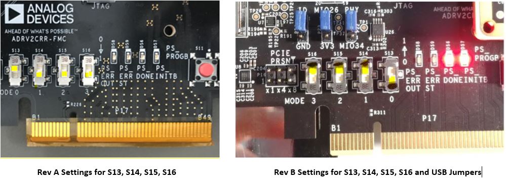
Configure ADRV2CRR-FMC for SD BOOT using S13, S14, S15, S16. See picture below.
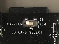
Configure ADRV2CRR-FMC for SD BOOT from carrier using S9. See picture below.
Turn on the power switch on the carrier board using S12.
Observe kernel and serial console messages on your terminal. (Use the first ttyUSB or COM port registered, Baud rate 115200 (8N1))
ZCU102
Connect the AD-FMCOMMS8-EBZ to the ZCU102 HPC0 connector.
Connect the 12V Power Supply.
Connect USB UART (Micro USB) to your host PC.
Insert SD card.
Turn on the power switch.
Observe kernel and serial console messages on your terminal. (Baud rate 115200 (8N1))
Testing
Make sure all devices are present
root@analog:~# iio_info | grep iio:device
       iio:device0: ams
       iio:device1: hmc7044-car
       iio:device10: axi-adrv9009-rx-obs-hpc (buffer capable)
       iio:device11: axi-adrv9009-tx-hpc (buffer capable)
       iio:device2: hmc7044-ext
       iio:device3: hmc7044-fmc
       iio:device4: hmc7044
       iio:device5: adrv9009-phy-c
       iio:device6: adrv9009-phy-d
       iio:device7: adrv9009-phy
       iio:device8: adrv9009-phy-b
       iio:device9: axi-adrv9009-rx-hpc (buffer capable)
Check clock chip lock status
root@analog:~# iio_attr -q -D hmc7044 status
--- PLL1 ---
Status: Locked
Using: CLKIN1 @ 30720000 Hz
PFD: 30720 kHz
--- PLL2 ---
Status: Locked (Synchronized)
Frequency: 2949120000 Hz (Autocal cap bank value: 13)
SYSREF Status:  Valid & Locked
SYNC Status:    Synchronized
Lock Status: PLL1 & PLL2 Locked
root@analog:~# iio_attr -q -D hmc7044-fmc status
--- PLL1 ---
Status: Locked
Using: CLKIN1 @ 30720000 Hz
PFD: 30720 kHz
--- PLL2 ---
Status: Locked (Synchronized)
Frequency: 2949120000 Hz (Autocal cap bank value: 14)
SYSREF Status:  Valid & Locked
SYNC Status:    Synchronized
Lock Status: PLL1 & PLL2 Locked
root@analog:~# iio_attr -q -D hmc7044-car status
--- PLL1 ---
Status: Locked
Using: CLKIN3 @ 38400000 Hz
PFD: 7680 kHz
--- PLL2 ---
Status: Locked (Unsynchronized)
Frequency: 2949120000 Hz (Autocal cap bank value: 14)
SYSREF Status:  Valid & Locked
SYNC Status:    Unsynchronized
Lock Status: PLL1 & PLL2 Locked
Note
hmc7044-car reporting Unsynchronized is expected — this chip is
only frequency locked against an external reference clock, not phase
synchronized.
For more information see:
Check JESD204B Link Status
root@analog:~# TERM=vt100 jesd_status -s
 (DEVICES) Found 3 JESD204 Link Layer peripherals

 (0): 84a50000.axi-jesd204-rx  [*]
 (1): 84a30000.axi-jesd204-tx
 (2): 84a70000.axi-jesd204-rx

 (STATUS)
 Link is                 enabled
 Link Status             DATA
 Measured Link Clock     245.763
 Reported Link Clock     245.760
 Lane rate               9830.400
 Lane rate / 40          245.760
 LMFC rate               7.680
 SYSREF captured         Yes
 SYSREF alignment error  No

 (LANE STATUS)
 Lane#                             0      1      2      3      4      5      6      7
 Errors                            0      0      0      0      0      0      0      0
 Latency (Multiframes/Octets)      2/38   2/37   2/41   2/39   2/41   2/40   2/39   2/39
 CGS State                         DATA   DATA   DATA   DATA   DATA   DATA   DATA   DATA
 Initial Frame Sync                Yes    Yes    Yes    Yes    Yes    Yes    Yes    Yes
 Initial Lane Alignment Sequence   Yes    Yes    Yes    Yes    Yes    Yes    Yes    Yes
For more information see JESD204B Status Utility.
Video Configuration
The default configuration for most projects uses HDMI output, but this project uses DisplayPort. Follow the steps described at DisplayPort - no picture? then reboot the board.
IIO Oscilloscope
The IIO Oscilloscope application can be used to remotely configure and monitor the ADRV9009 transceivers. See IIO Oscilloscope for details.
Important
Always shut down the board gracefully to avoid SD card corruption:
root@analog:~# sudo shutdown -h now