Dual Triton MultiChip Sync (MCS) Pilot Overview
This section provides the steps required to setup the Dual Triton MCS Demo, which consists of two 16T/16R Triton Development Platforms and a Aion (ADF4030) Evaluation Board. The pilot demonstrates the usage of the Aion sync device to align the BSYNCs from the EVAL-ADF4030 and have these drive each Triton as external BSYNC inputs. The pilot then has the Leader Triton transmit a DAC signal and loop it back into one of its own ADCs and also send it to an ADC on the Follower Triton. The ADC data from both platforms are then post processed and the delay calculated to demonstrate accuracy of +/-5 picoseconds.
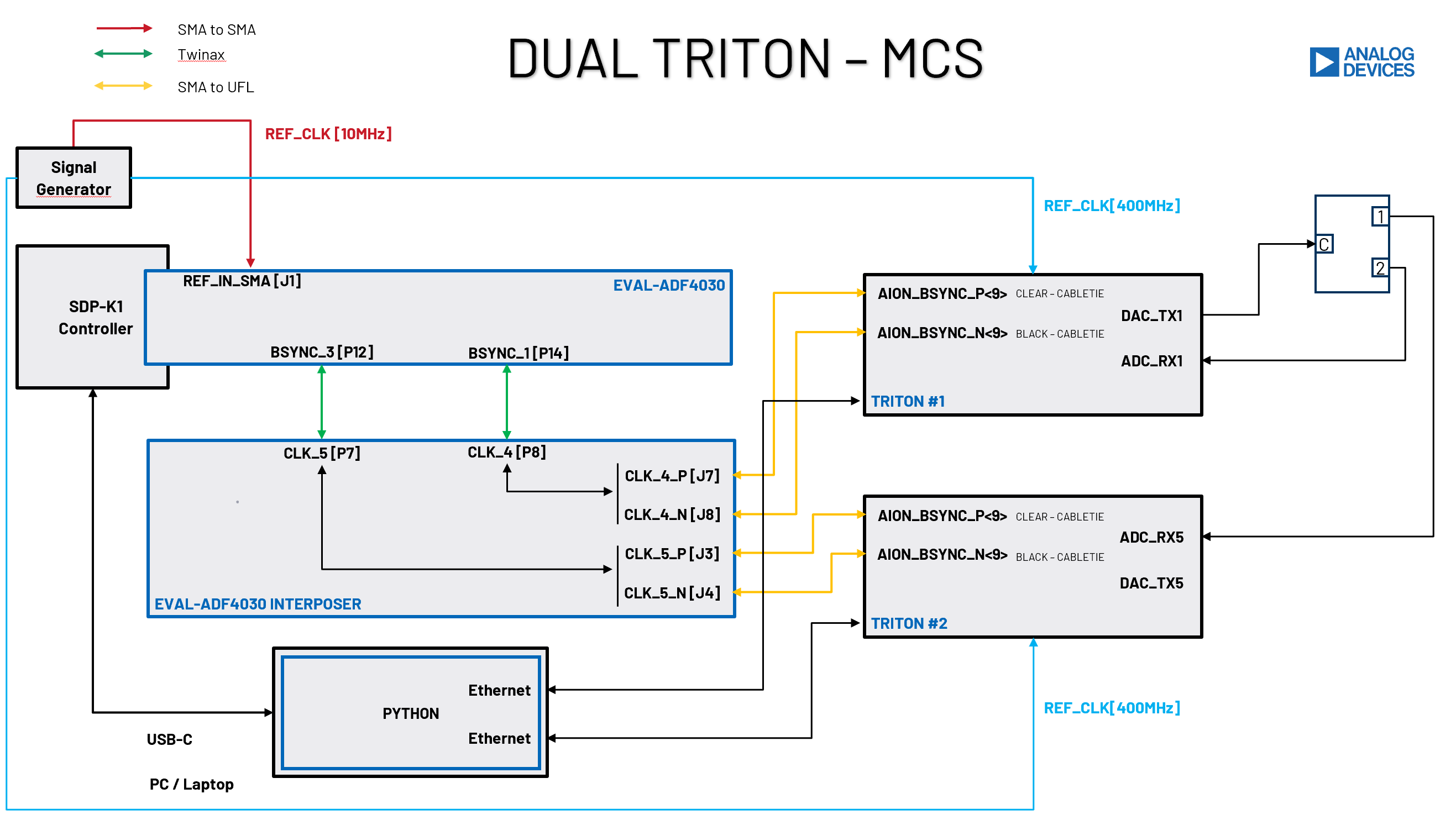
Block Diagram
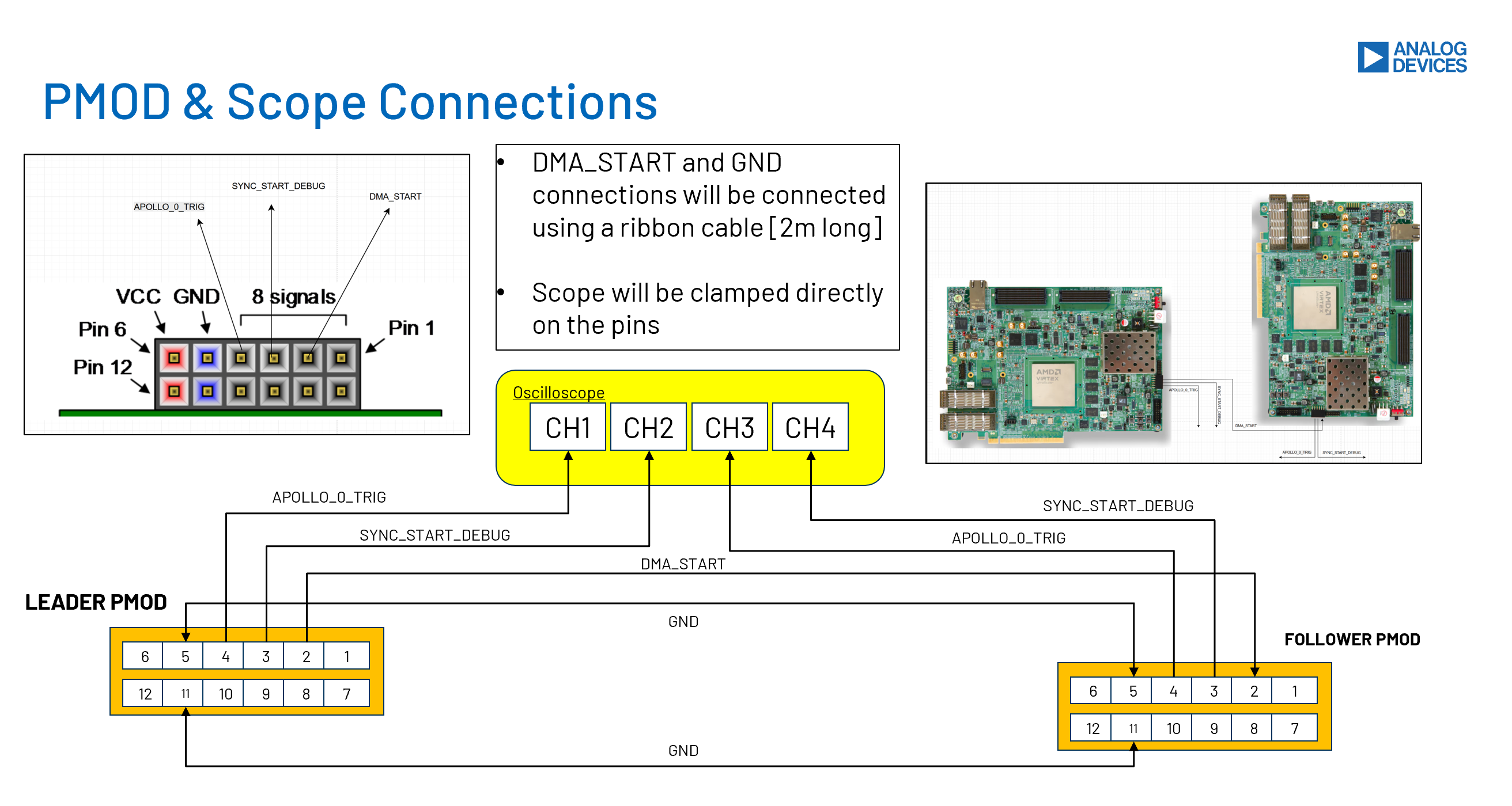
The figure below provides a high level block diagram of the required connections for the system as well as the PMOD connections required for triggering of the system.
Hardware Requirements
The following hardware is needed to successfully setup this pilot:
1 x RF Signal Generator supporting up to 400MHz as a reference frequency for each Triton
1 x RF Power Splitter to distribute the 400MHz to each Triton 2-Way Power Splitter 0.5 - 600MHz (Mini-Circuits)
1 x RF Power Splitter to distribute the DAC Transmission at X-Band to the Leader & Follower ADC’s 4-Way Power Splitter 500 - 26500 MHz (Mini-Circuits)
Software Requirements
As there are two Triton Platforms used in this pilot, one as a Leader and the other a Follower, we need to load these with two different HDL images.
Warning
Weblinks must be updated following release - placeholder only
Bring Up Steps
Note
This resource list is regularly updated. For the most current information and additional resources, please visit the individual product pages and the ADI wiki.