Triton Platform Initialization
This section will cover the setup and initialization of the Triton Platform
Note
It is assumed that the user has gone through the standard bring up documentation for Triton as outlined earlier. If this is not the case please return to the Triton Home Page and familiarize yourself with this before executing the Dual Triton MCS Pilot.
As outlined earlier in the Software Requirements section, there are different images for Triton #1 (Leader) and Triton #2 (Follower). You should follow this list of steps to bring up the Triton Hardware ahead of script execution.
400MHz REF Clock Connection
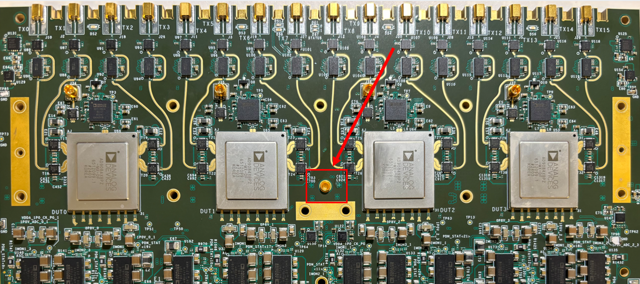
As outlined in the documentation earlier, each of the Triton boards needs to have a 400 MHz REF_CLOCK connected to the board before the system is powered on. This should be connected to SMP RF Connector J34 as shown below on each of the boards. As per the block diagram, both Tritons should have the same 400MHz source through an RF Splitter.
Once this clock is connected to the Triton Platforms, you can move to the next step
Triton #1 JTAG Programming & Boot Up
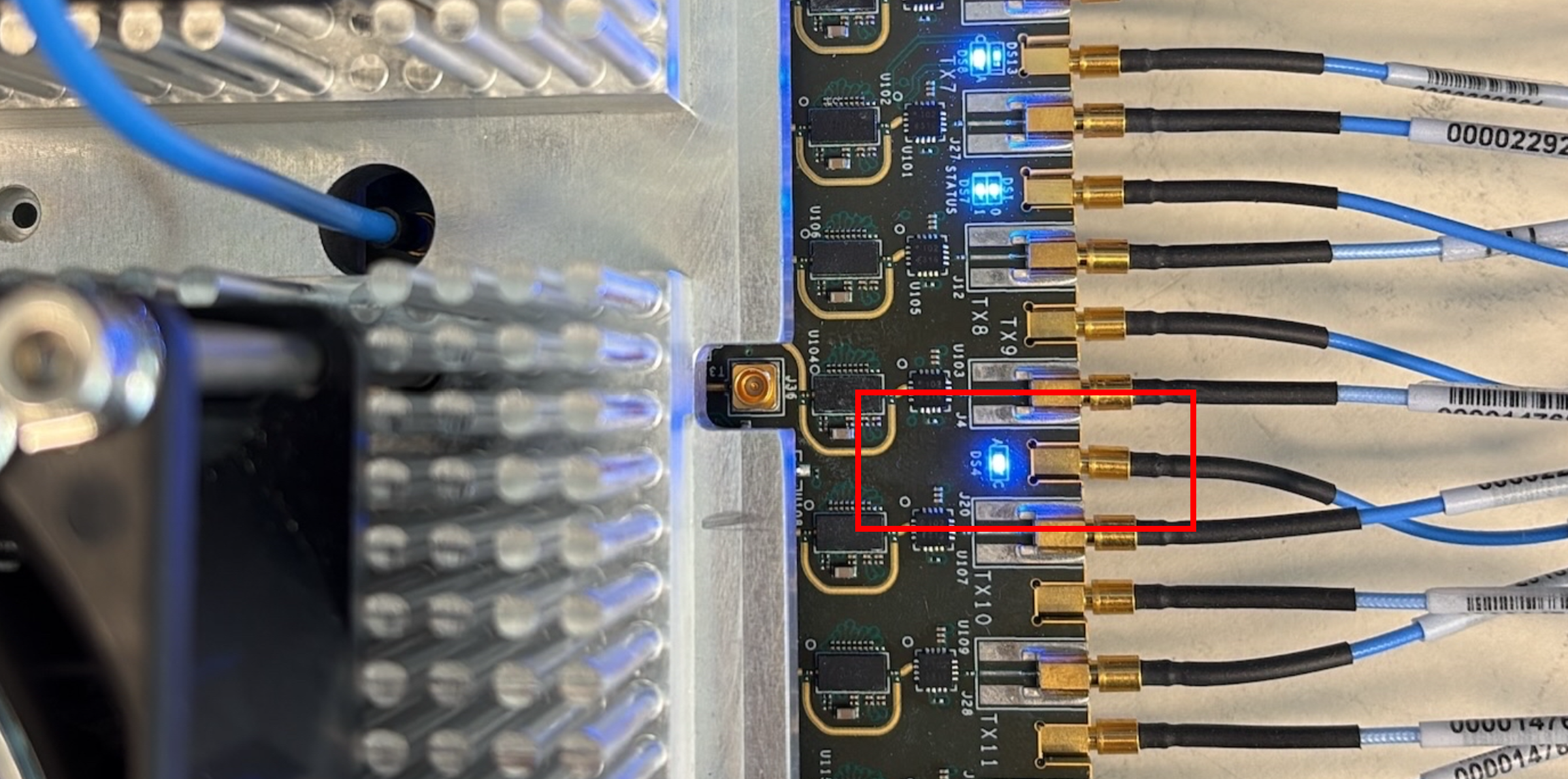
With the 400 MHZ REF_CLK connected, you can now power up the VCU118 and the Triton #1 Board. You should observe the Fans turning on above the Triton Heatsink and you should also see a blue LED illuminated confirming that the 400 MHz clock is connected correctly, reference the image below
Triton #1 JTAG Programming
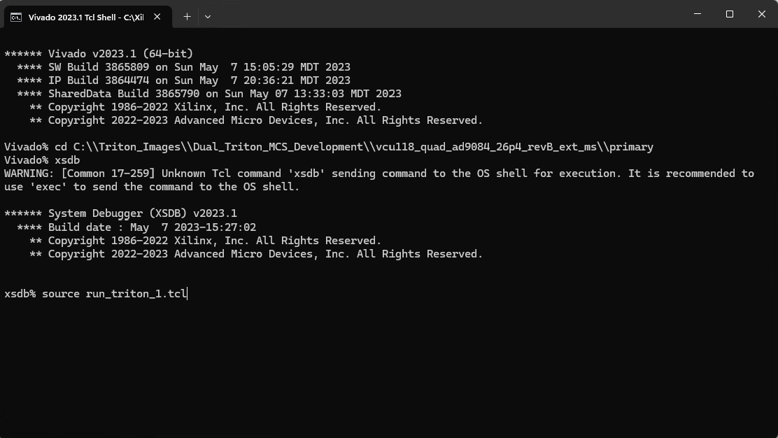
On your PC, open a Vivado 2023.1 Tcl Shell, this will appear similar to a cmd or powershell window. It will communicate with the VCU118 over USB JTAG and program the FPGA and Microblaze image after which the Triton Platform will boot to Linux. You should also open a COMM port connection to the Triton #1 board, this can be identified in your PC’s Device Manager.
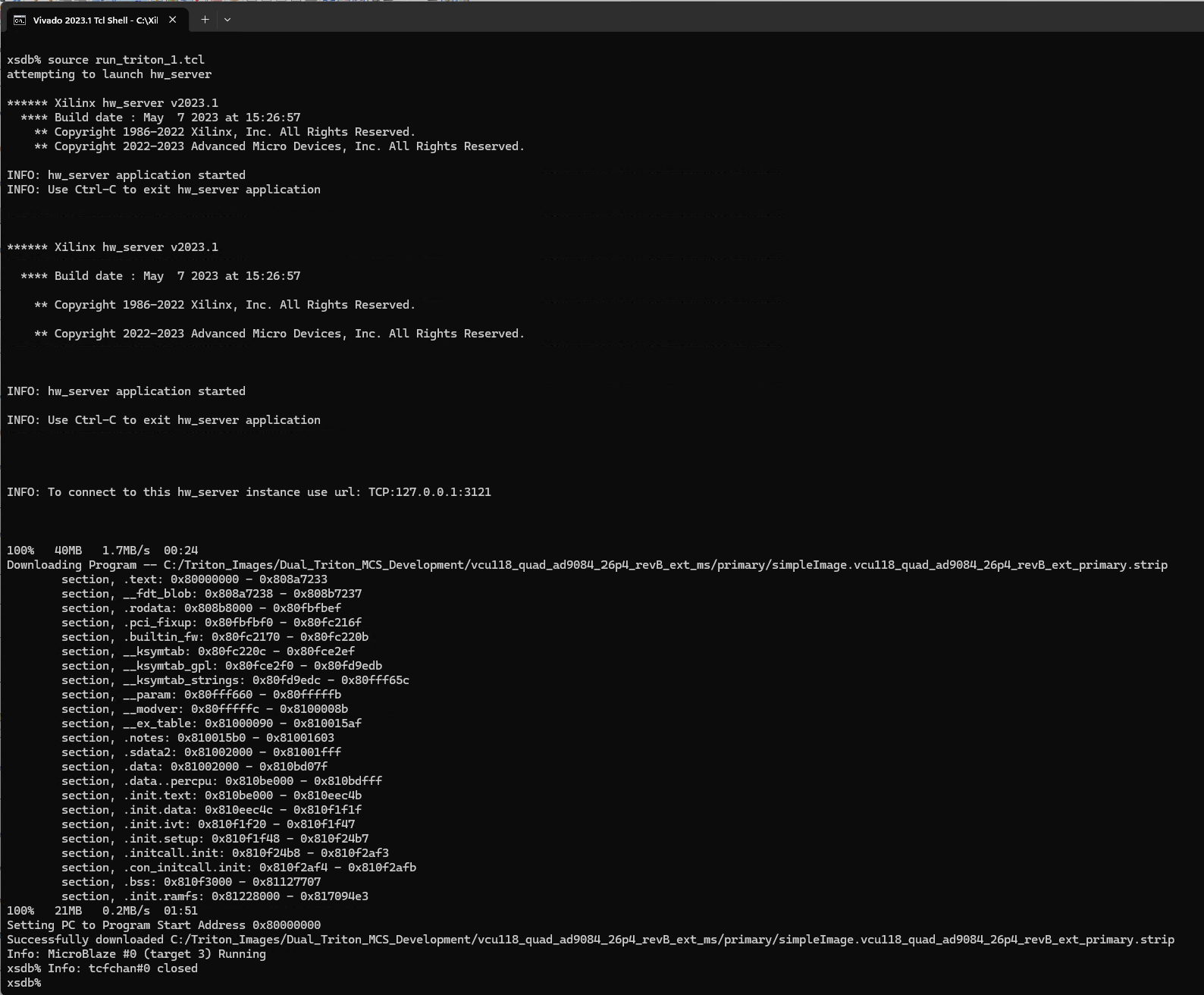
With the Vivado Tcl Shell open, you need to navigate to the location where you have stored the primary Triton image, load the debug shell and then program the platform. This can be achieved using the following commands. Reference the images below for guidance on pre-programming commands as well as expected response.
cd C:\\Triton_Images\\Dual_Triton_MCS_Development\\vcu118_quad_ad9084_26p4_revB_ext_ms\\primary

xsdb

source run_triton_1.tcl
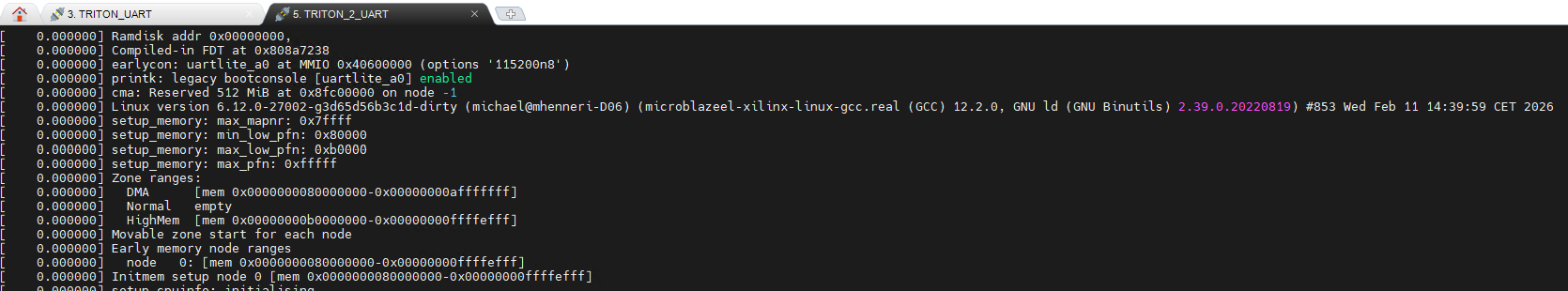
Triton #1 UART Boot Up Verification
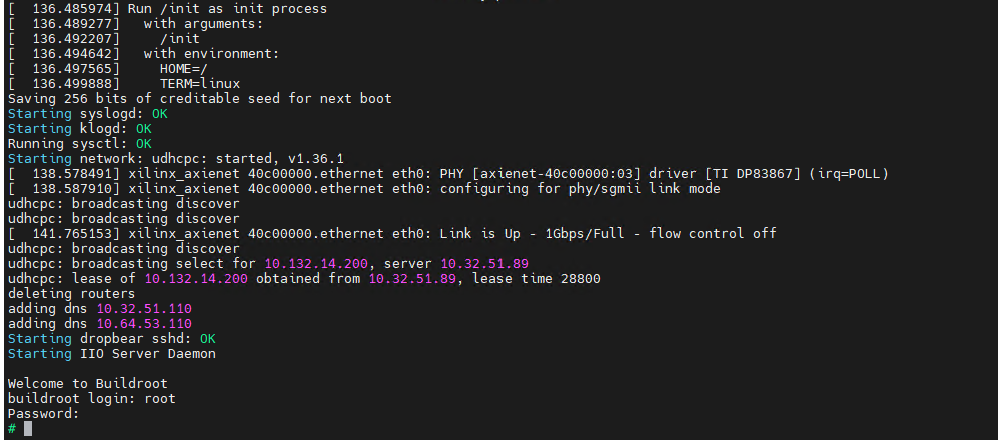
Having successfully programmed the Triton Platform over JTAG, you should move to monitor the COMM port console using the application of your choosing, e.g. Putty. As shown in the screenshots below, you will see an initial console output and then after about 2.5 mins, the system will complete its boot up sequence and you will be prompted to login to the system.
Username: root

Password: analog
Triton #2 JTAG Programming & Boot Up
With the 400 MHZ REF_CLK connected, you can now power up the VCU118 and the Triton #2 Board. You should observe the Fans turning on above the Triton Heatsink and you should also see a blue LED illuminated confirming that the 400 MHz clock is connected correctly, reference the image below.
Triton #2 JTAG Programming
On your PC, open a Vivado 2023.1 Tcl Shell, this will appear similar to a cmd or powershell window. It will communicate with the VCU118 over USB JTAG and program the FPGA and Microblaze image after which the Triton Platform will boot to Linux. You should also open a COMM port connection to the Triton #2 board, this can be identified in your PC’s Device Manager.
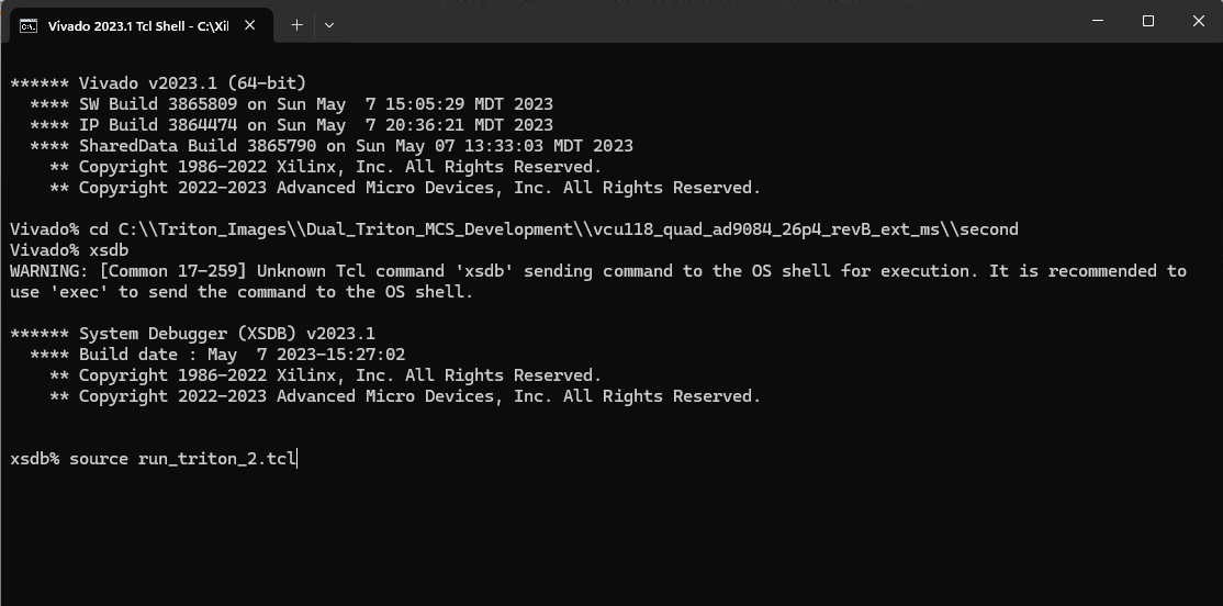
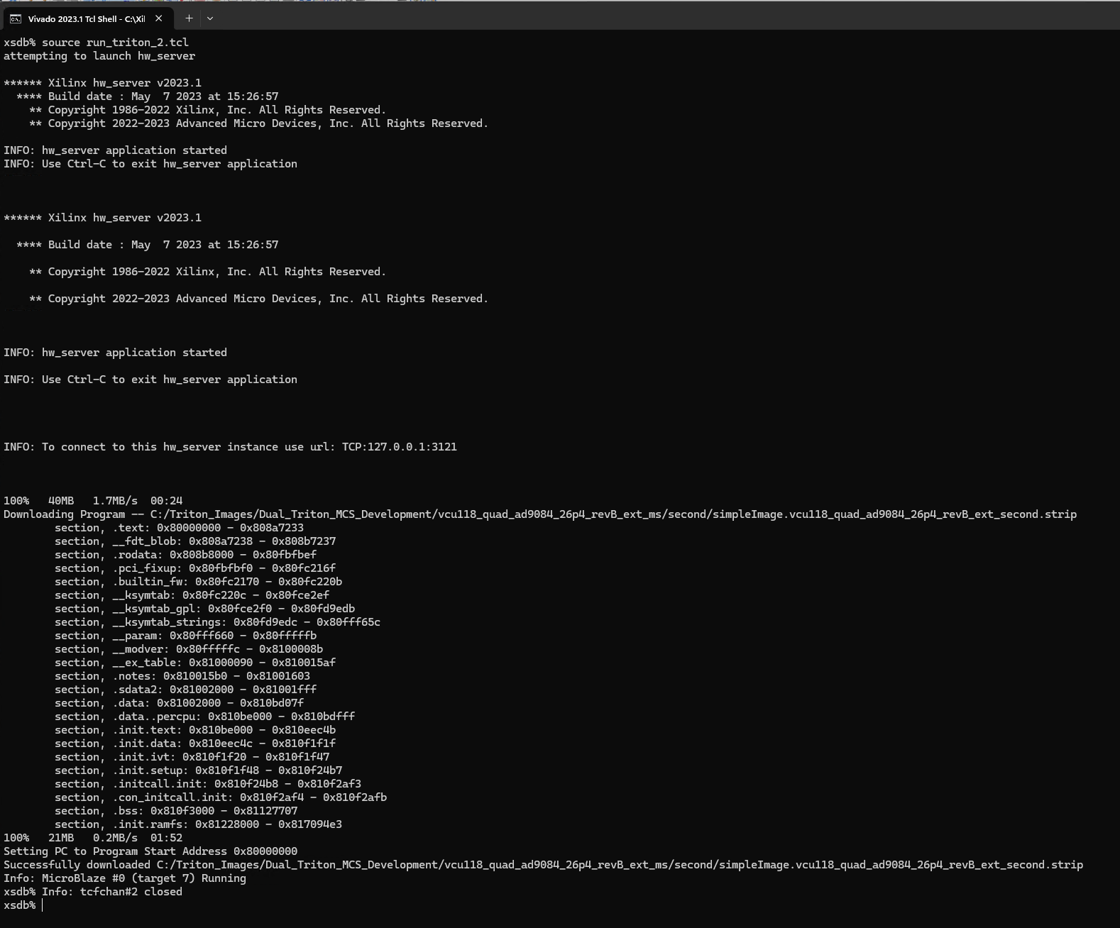
With the Vivado Tcl Shell open, you need to navigate to the location where you have stored the second Triton image, load the debug shell and then program the platform. This can be achieved using the following commands. Reference the images below for guidance on pre-programming commands as well as expected response.
cd C:\\Triton_Images\\Dual_Triton_MCS_Development\\vcu118_quad_ad9084_26p4_revB_ext_ms\\second

xsdb

source run_triton_2.tcl
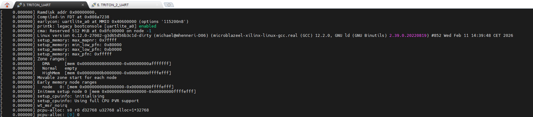
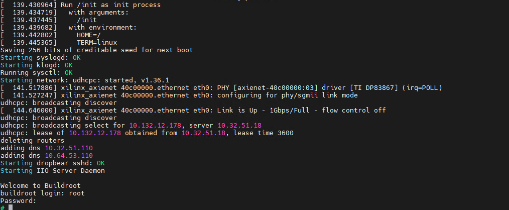
Triton #2 UART Boot Up Verification
Having successfully programmed the Triton Platform over JTAG, you should move to monitor the COMM port console using the application of your choosing, e.g. Putty. As shown in the screenshots below, you will see an initial console output and then after about 2.5 mins, the system will complete its boot up sequence and you will be prompted to login to the system.
Username: root

Password: analog
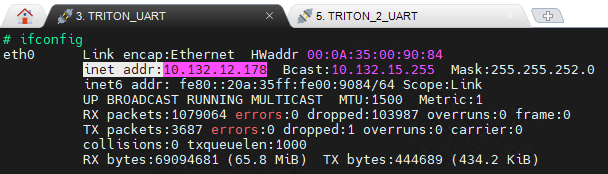
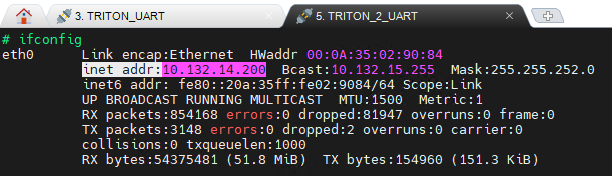
IP Address Verification
Primary and Secondary images for this pilot have configured the platforms to have independent MAC Addresses to ensure that each of the platforms are assigned independent IP Addresses to ensure independent control. We can check what these IP addresses using the ifconfig on each of the UART consoles and we note the address as it will be needed for the Python code execution.
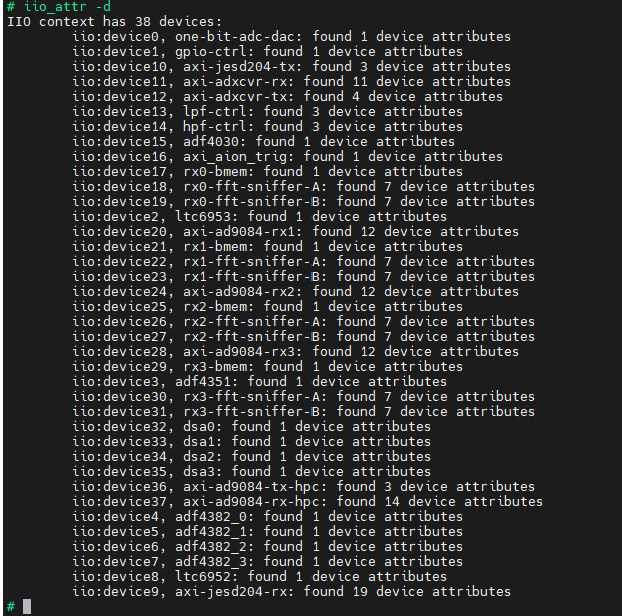
IIO Device Verification
The Python scripts will communicate using Pyiio so we need to ensure that we have the expected devices listed on each of the systems. We can check these using the iio_attr -d and review the response for the expected 38 devices as shown below.
IMPORTANT: If you do not see the same number of devices, please check that you have loaded the correct image.
JESD Status Verification
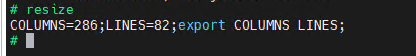
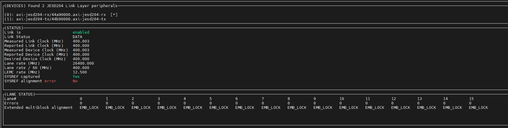
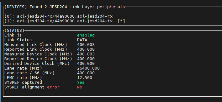
The last check we need to execute on each of the platforms before moving to the Python code execution is to check the JESD status. We can check this using the jesd_status command and this will show the status for both DAC’s and ADC’s. You can toggle between the two using the ‘a’ key. Ahead of running the command however, to ensure the formatting of the response is correct, we need to send a resize command to the UART terminal.
For both the ADC and DAC JESD Status’, the checks you are looking for are:
Ensure the Link is response is enabled
Ensure the Link Status response is DATA
Ensure the Device and Link Clocks are response is 400 MHz approx
Ensure the Lane Rate MHz response is 26400.000
Ensure the Lane Rate / 66 MHz response is 400.000
Ensure the SYSREF captured response is Yes
Ensure the SYSREF alignment error response is No
ONCE THE ABOVE CHECKS ARE COMPLETED SUCCESSFULLY MOVE TO THE PYTHON SCRIPT SETUP & EXECUTION