ZedBoard Quick Start
All the products described on this page include ESD (electrostatic discharge) sensitive devices. Electrostatic charges as high as 4000V readily accumulate on the human body or test equipment and can discharge without detection. Although the boards feature ESD protection circuitry, permanent damage may occur on devices subjected to high-energy electrostatic discharges. Therefore, proper ESD precautions are recommended to avoid performance degradation or loss of functionality. This includes removing static charge on external equipment, cables, or antennas before connecting to the device.
This guide provides step by step instructions on how to set up the EVAL-AD5766-SD2Z on:
ZedBoard The supported revision is C or higher.
Using no-OS as software
Necessary files
The following files are needed for the system to boot:
HDL boot file:
system_top.xsano-OS project: projects/ad5766-sdz
Instructions on how to build the boot files from source can be found below:
AD5766-SDZ no-OS Example Project. More no-OS build details at No-OS Build Guide.
AD5766-SDZ HDL project. More HDL build details at Build an HDL project.
Required software
AMD Xilinx Vivado and Vitis (downloading Vitis from here will include Vivado as well)
An UART terminal (Putty/Tera Term/Minicom, etc.), Baud rate 115200 (8N1)
Required hardware
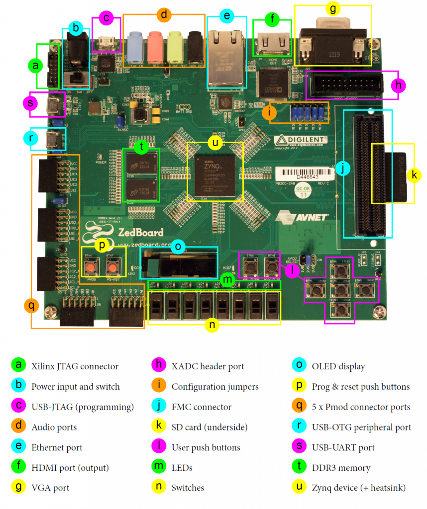
ZedBoard Rev C or later
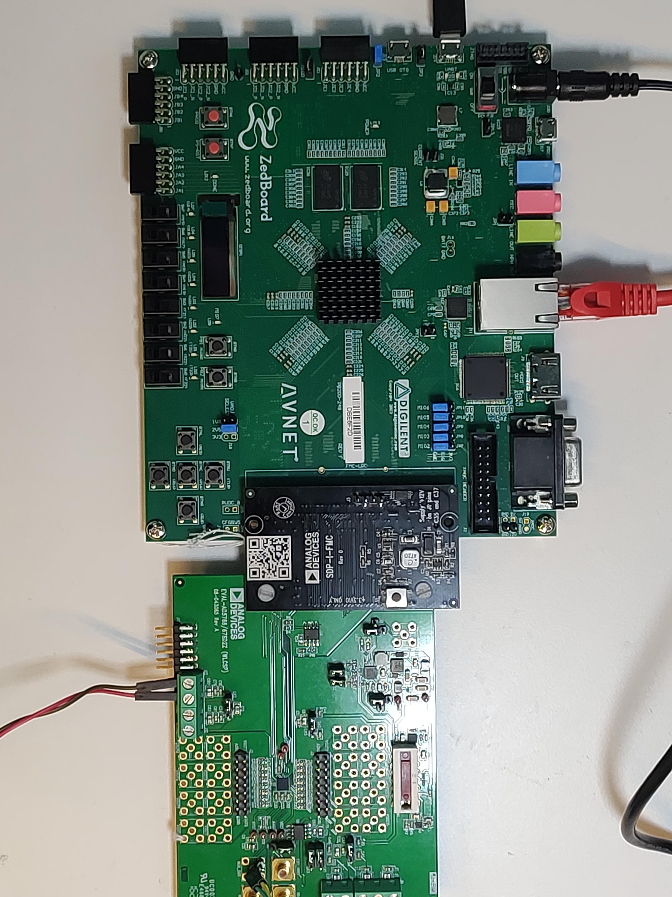
EVAL-AD5766-SD2Z FMC evaluation board
2x Micro-USB cables, one for UART and one for JTAG
SDP-FMC Interposer
Oscilloscope
External 3.3V Voltage Source
More details as to why you need these, can be found at Prerequisites.
Testing
Creating the setup
All the products described on this page include ESD (electrostatic discharge) sensitive devices. Electrostatic charges as high as 4000V readily accumulate on the human body or test equipment and can discharge without detection. Although the boards feature ESD protection circuitry, permanent damage may occur on devices subjected to high-energy electrostatic discharges. Therefore, proper ESD precautions are recommended to avoid performance degradation or loss of functionality. This includes removing static charge on external equipment, cables, or antennas before connecting to the device.
Steps:
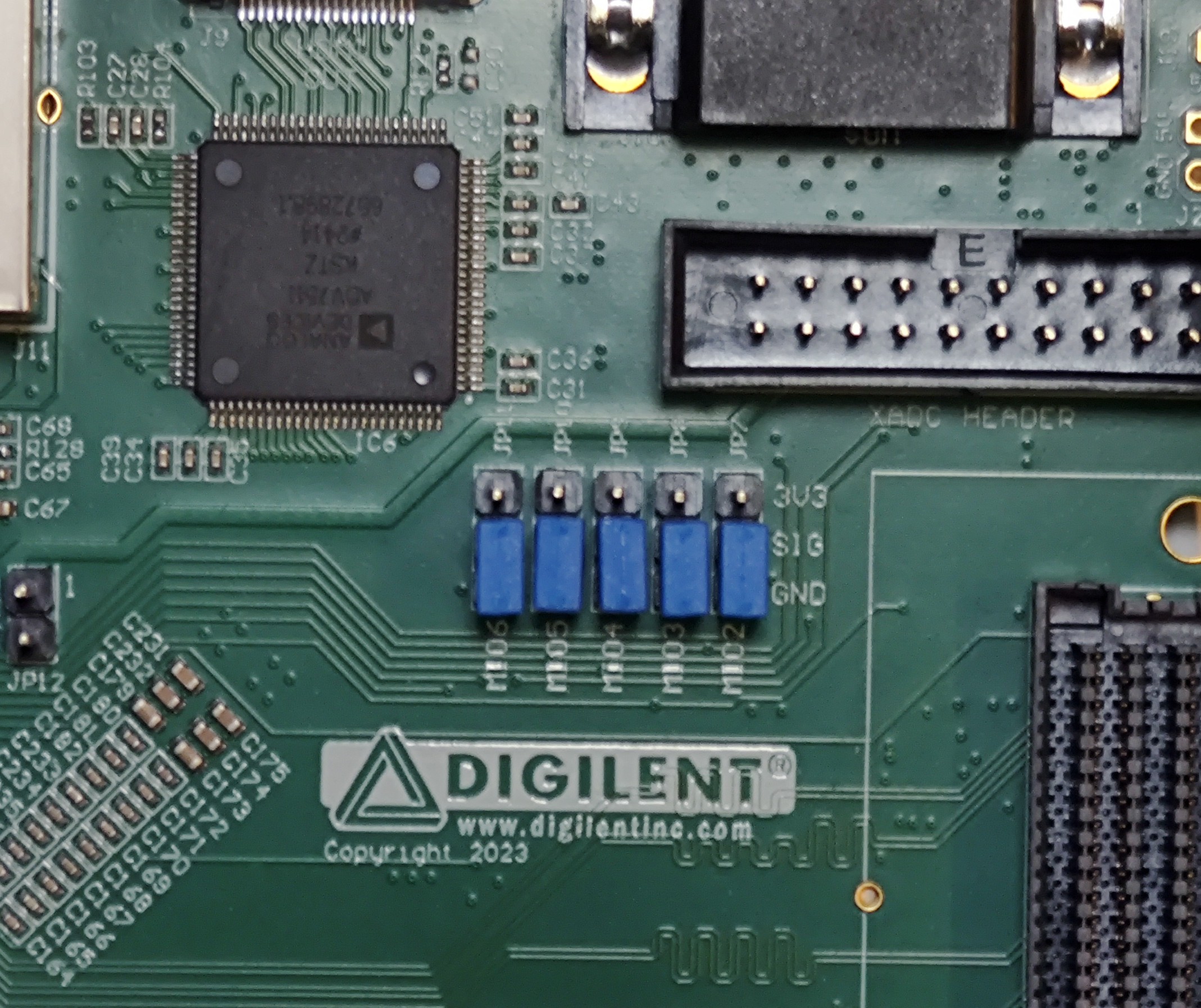
Set the ZedBoard jumpers to No-OS configuration (all of the configuration jumpers to GND).
- Connect the ZedBoard to your desktop with 2 Micro-USB cables.
One for UART (J14)
One for JTAG (J17)
Connect the barrel jack power supply to the ZedBoard.
Make sure the VADJ is set to 2V5.
Make sure the jumpers on the evaluation board are set for your desired configuration. The configuration in this quickstart guide is:
Jumper |
Position |
|---|---|
LK1 |
A |
LK2 |
A |
LK3 |
A |
LK4 |
B |
LK5 |
B |
LK6 |
B |
LK7 |
A |
LK8 |
B |
LK9 |
A |
LK10 |
A |
LK11 |
Set |
LK12 |
Set |
Connect the Evaluation Board to the ZedBoard by using a SDP to FMC interposer on the FMC connector of the ZedBoard (J1).
Connect a 3.3V Voltage Source to the J12 Connector of the Evaluation Board.
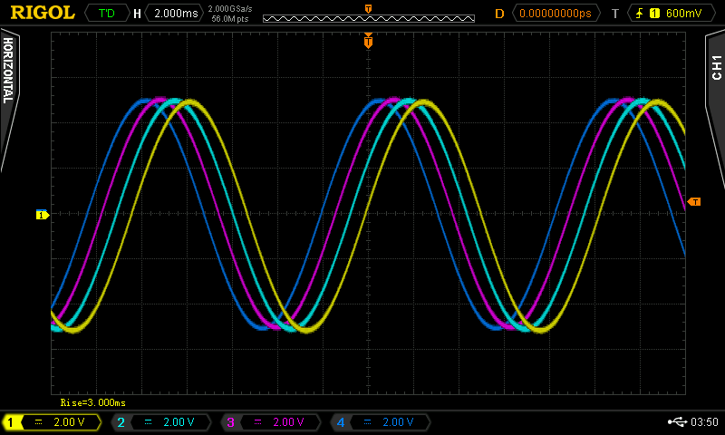
Connect an oscilloscope to the MUX_OUT Connector of the Evaluation Board.
Build the boot files and run the project. You can follow this guide
Using the oscilloscope check your output.
See also
For more detailed information on ZedBoard jumper settings, check the ZedBoard Hardware User Guide (chapter “Configuration modes”) here.
Console output
The following is what is printed in the serial console, after you have connected to the proper ttyUSB or COM port:
- ::
<Placeholder>