

AD4080-FMC-EVB HDL project
Caution
Although the AD4080 supports CMOS interface, this HDL project does not support it. The only available interface for this project is LVDS, in DDR mode. Single lane mode is fully tested and supported. Dual lane mode is supported in the HDL but has not been tested yet.
The EVAL-AD4080-FMC is designed to demonstrate the AD4080 performance.
The EVAL-AD4080-FMC HDL design supports the following AD4080, AD4083, AD4086 features:
Single lane DDR data capture
Self synchronization using the fixed pattern and bit-slip feature
Capturing digital averaging filter with up to 2^10 decimation
Analog-to-digital converter (ADC) configuration via serial peripheral interface (SPI)
Sampling rate capability between 1.25 MSPS and 40 MSPS
The EVAL-AD4080-FMC evaluation board was designed for use with the Digilent ZedBoard via the field programmable gate array(FPGA) mezzanine card (FMC) connector.
Supported boards
Supported devices
Supported carriers
Evaluation board |
Carrier |
FMC slot |
|---|---|---|
FMC-LPC |
Block design
Warning
The VADJ for the Zedboard must be set to 2.5V.
Block diagram
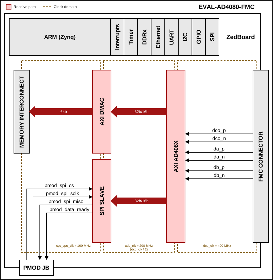
The data path and clock domains are depicted in the below diagram:

SPI slave interface
The optional SPI slave interface is enabled at build time with the
SPI_SLAVE=1 make parameter. It instantiates the SPI Slave IP,
which buffers the captured ADC samples in an asynchronous FIFO and streams
them out to an external SPI master over the ZedBoard PMOD JB header,
independently of the DMA data path. This lets a device that is not on the
processor bus (for example a microcontroller acting as an SPI controller)
read the ADC data without involving the processor or the DMA.
Block name |
IP name |
Documentation |
Additional info |
|---|---|---|---|
AXI AD408X |
Instance |
||
AXI DMAC |
Instance |
||
SPI SLAVE |
Instance |
The SPI slave operates in Mode 3 (clock idles high), MSB first, and only
sources data (there is no MOSI). The external master polls
pmod_data_ready to know when a new sample is available and frames each
read as a single transfer. The signals are routed to the PMOD JB header
using the LVCMOS33 I/O standard, as follows:
Signal |
PMOD JB pin |
FPGA pin |
Direction (FPGA view) |
|---|---|---|---|
|
JB1 |
W12 |
Input |
|
JB2 |
W11 |
Input |
|
JB3 |
V10 |
Output |
|
JB4 |
W8 |
Output |
Clock scheme

CPU/Memory interconnects addresses
The addresses are dependent on the architecture of the FPGA, having an offset added to the base address from HDL (see more at CPU/Memory interconnects addresses).
Instance |
Zynq/Microblaze |
|---|---|
axi_ad4080_adc |
0x44A0_0000 |
axi_ad4080_dma |
0x44A3_0000 |
SPI connections
SPI type |
SPI manager instance |
SPI subordinate |
CS |
|---|---|---|---|
PS |
SPI 0 |
AD4080 |
0 |
PS |
SPI 1 |
AD9508 |
0 |
PS |
SPI 1 |
ADF4350 |
1 |
GPIOs
To know how the Software GPIO numbers are calculated, check out GPIOs - HDL Architecture page.
GPIO signal |
Direction |
HDL no. |
Zynq-7000 |
|---|---|---|---|
ad9508_sync |
OUT |
37 |
91 |
pwrgd |
IN |
36 |
90 |
adf435x_lock |
INOUT |
35 |
89 |
gpio3_fmc |
INOUT |
34 |
88 |
gpio2_fmc |
INOUT |
33 |
87 |
Legend
GPIO signal = name of the GPIO in the HDL project
Direction = from the FPGA point of view
HDL no. = HDL GPIO EMIO
Zynq-7000 = Software GPIO, to be used in device trees
Interrupts
Below are the Programmable Logic interrupts used in this project.
Instance name |
HDL |
Linux Zynq |
Actual Zynq |
|---|---|---|---|
axi_ad4080_dma |
13 |
57 |
89 |
Building the HDL project
The design is built upon ADI’s generic HDL reference design framework. ADI distributes the bit/elf files of these projects as part of the ADI Kuiper Linux. If you want to build the sources, ADI makes them available on the HDL repository. To get the source you must clone the HDL repository, and then build the project as follows:
Linux/Cygwin/WSL
Example of running the make command without parameters (using the default
configuration (ADC_N_BITS=20):
~$
cd hdl/projects/ad4080_fmc_evb/zed
~/hdl/projects/ad4080_fmc_evb/zed$
make
Example of running the make command with parameters:
~$
cd hdl/projects/ad4080_fmc_evb/zed
~/hdl/projects/ad4080_fmc_evb/zed$
make ADC_N_BITS=16
Example of running the make command with the optional SPI slave interface
enabled on the PMOD JB header:
~$
cd hdl/projects/ad4080_fmc_evb/zed
~/hdl/projects/ad4080_fmc_evb/zed$
make SPI_SLAVE=1
The following table contains the parameters that can be used to configure this project:
Parameter |
Description |
|---|---|
ADC_N_BITS |
ADC resolution (default: 20)
|
SPI_SLAVE |
Add the optional SPI slave (PMOD JB) interface (default: 0)
|
A more comprehensive build guide can be found in the Build an HDL project user guide.
Resources
More information
Support
Analog Devices, Inc. will provide limited online support for anyone using the reference design with ADI components via the EngineerZone FPGA reference designs forum.
For questions regarding the ADI Linux device drivers, device trees, etc. from our Linux GitHub repository, the team will offer support on the EngineerZone Linux software drivers forum.
For questions concerning the ADI No-OS drivers, from our No-OS GitHub repository, the team will offer support on the EngineerZone microcontroller No-OS drivers forum.
It should be noted, that the older the tools’ versions and release branches are, the lower the chances to receive support from ADI engineers.