A10SoC Quick start
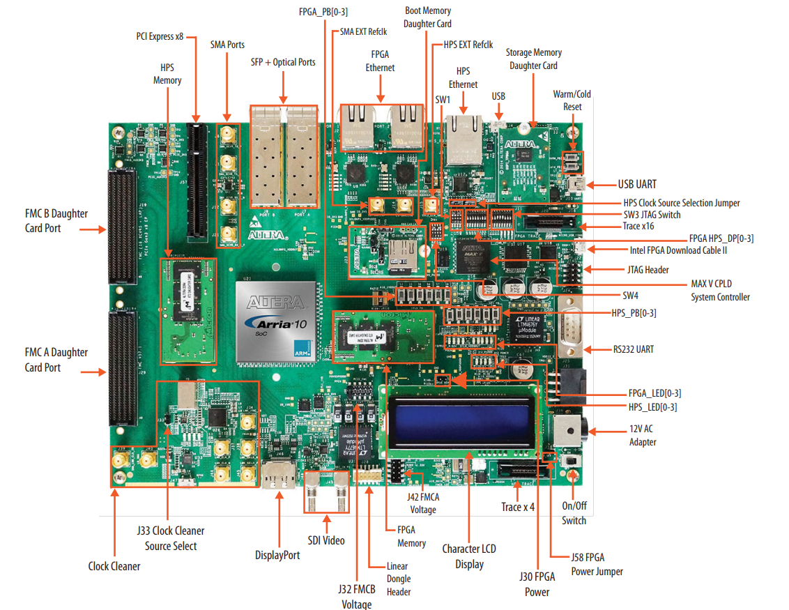
This guide provides quick instructions on how to setup the EVAL-ADRV9002 on:
Arria 10 SoC (Rev. C or later) on FMCA
Using Linux as software
Necessary files
Note
For Intel SoC-FPGA boards, one boot file must be written to the third SD card partition, which is not accessible from Windows. You will need either a native Linux system or WSL to properly configure the SD card. For detailed file placement instructions, refer to Using Kuiper Linux pre-built images.
On the Kuiper image, the zImage file and the extlinux.conf file can be found
in the carrier-specific folder, which is common to all projects that use this
carrier. All remaining boot files are located in the project-specific folder.
The extlinux directory is not provided and must be created by the user.
The following files are needed for the system to boot:
HDL boot image:
fit_spl_fpga.itbLinux Kernel image:
zImageLinux device tree:
socfpga_arria10_socdk_sdmmc.dtbU-Boot image:
u-boot.imgextlinux.confin the extlinux folder from SD CardWrite
u-boot-splx4.sfpon third SD Card partition:
Instructions on how to manually build the boot files from source can be found here:
Building the Intel SoC-FPGA kernel and devicetrees from source
ADRV9001 HDL Project build documentation. More HDL build details at Build an HDL project.
Required software
SD Card 16GB imaged with Kuiper
A UART terminal (Putty/Tera Term/Minicom, etc.) with baud rate 115200 (8N1)
Required hardware
Arria 10 SoC (Rev. C or later) FPGA board and its power supply
EVAL-ADRV9002 FMC evaluation board
MicroSD card with at least 16GB of memory
Mini-USB cable (UART)
LAN cable (Ethernet)
Signal generator
Signal analyzer
Signal synthesizer (required only if using external clock source)
1x SMA cable for signal generator
1x SMA cable for signal analyzer
1x SMA cable for signal synthesizer (if using external clock)
(Optional) USB keyboard & mouse and a HDMI compatible monitor
More details as to why you need these, can be found at Prerequisites.
A10SoC required hardware changes
Warning
The following rework is required on the A10SoC FPGA:
To avoid using an external clock source and fully rely on the HMC7044 clock chip, rotate the C6D/C4D caps in C5D/C3D position. (Please note: In the latest version of the board, this is now the default configuration, so this configuration step might not be needed anymore).
If LEDS V1P0_LED and VINT_LED are not on please depopulate R22M and populate R2M.
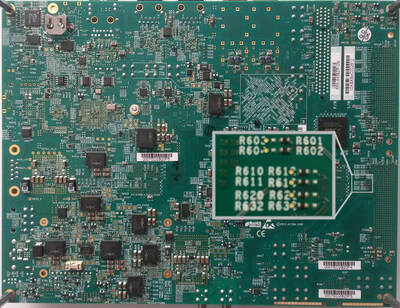
In the default configuration of the Arria10 SoC Development Kit, some of the FMC header pins are connected to a dedicated clock chip. To be compatible with the EVAL-ADRV9002, these pins need to be connected directly to the FPGA.
The connection of those pins can be changed by moving the position of four zero Ohm resistors:
R612 to R610
R613 to R611
R621 to R620
R633 to R632
These resistors can be found on the backside of the A10SoC, underneath the FMCA connector (J29). The following picture shows the required configuration to be compatible with the EVAL-ADRV9002.
Testing
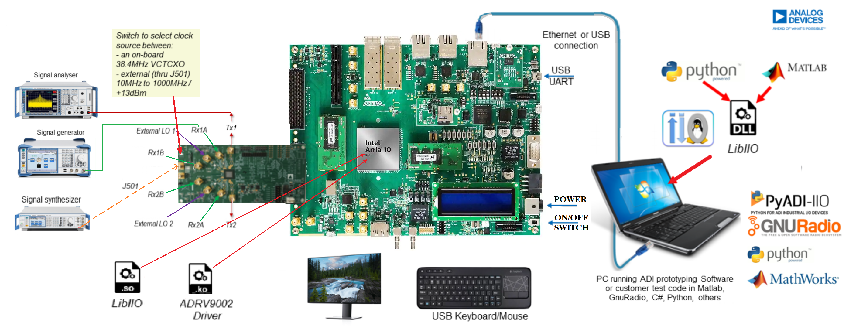
Creating the setup
All the products described on this page include ESD (electrostatic discharge) sensitive devices. Electrostatic charges as high as 4000V readily accumulate on the human body or test equipment and can discharge without detection. Although the boards feature ESD protection circuitry, permanent damage may occur on devices subjected to high-energy electrostatic discharges. Therefore, proper ESD precautions are recommended to avoid performance degradation or loss of functionality. This includes removing static charge on external equipment, cables, or antennas before connecting to the device.
Warning
Before executing the steps below, VADJ for FMCA must be set to 1.8V. Short pins 9 and 10 on J32 (default position).
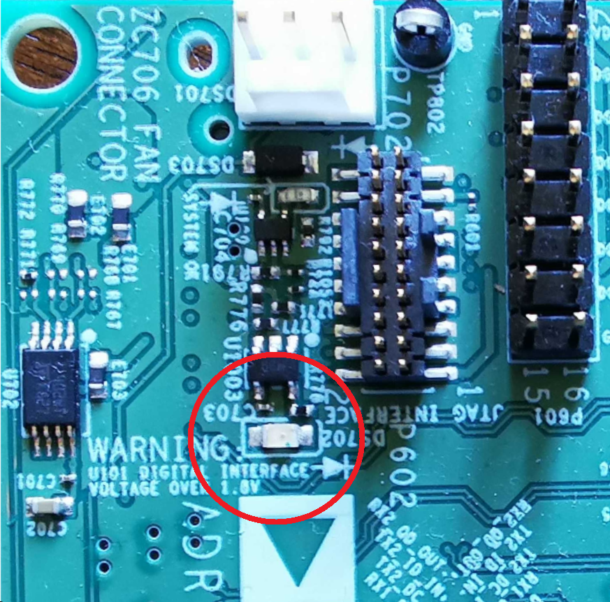
On the ADRV9002 card, there is a red LED close to the FMC connector. This LED indicates if VADJ voltage exceeded 2.0V. If the LED does not turn off after a few seconds after boot, VADJ is exceeding the recommended level, decreasing board lifetime and potentially causing permanent damage to the IC.
Follow the steps in this order, to avoid damaging the components:
Connect the EVAL-ADRV9002 FMC board to the FMCA carrier socket (G14).
On the FMC card, set the switch to select clock source between:
an on-board 38.4 MHz VCTCXO (default)
external (via J501) 10 MHz to 1000 MHz / +13 dBm
Connect USB UART (Mini-USB) to your host PC (J10).
Insert MicroSD card into socket.
Configure the Arria 10 SoC Development Kit for SD card booting (set the jumpers and switches accordingly).
Connect the power supply for the FPGA.
Turn on the power switch on the FPGA board.
Observe kernel and serial console messages on your terminal.
See also
For more detailed information on a10soc jumper configuration, check the A10SoC Hardware User Guide (chapter “Default Switch and Jumper Settings”) here.
Useful commands for the serial terminal
The below commands are to be run in the serial terminal connected to the FPGA.
To find out the IP of the FPGA board, run the following command and take the IP specified at “eth0 inet”:
~$
ifconfig
If the A10Soc is connected to a network with a DHCP server, the IP address assigned to the board appears on the LCD. To manually assign an IP address, run ifconfig eth0 IP_ADDR.
To see the IIO devices detected, run:
~$
iio_info | grep iio:device
To power off the system, run the following command, and wait for the final message to be printed, then power off the FPGA board from the switch as well.
~$
poweroff
To reboot the system, run:
~$
reboot
Important
Even though this is Linux, this is a persistent file system. Care should
be taken not to corrupt the file system – please shut down properly, don’t
just turn off the power switch. Depending on your monitor, the standard
power off could be hiding. You can do this from the terminal as well with
sudo shutdown -h now or the above-mentioned command for powering off.