ADRV9002 Plugin Description
The ADRV9002 plugin works with the IIO Oscilloscope. Always use the latest available version. Any field change is immediately written to the ADRV9002 hardware and then read back to verify the setting is valid. If a value you enter is changed by the GUI, it indicates either GUI rounding or that the hardware (ADRV9002 or FPGA fabric) does not support that specific mode or precision.
If you modify settings directly through /sys/bus/iio/devices/... outside of
the GUI, you can refresh the displayed values by clicking the
Reload Settings button at the bottom of the GUI.
The ADRV9002 view is divided in four sections:
ADRV9002 Global Settings
ADRV9002 Receive Chain
ADRV9002 Transmit Chain
FPGA Settings
See also
For more information about anything discussed in the sections below, see the ADRV9002 Linux Driver Documentation.
ADRV9002 Global Settings
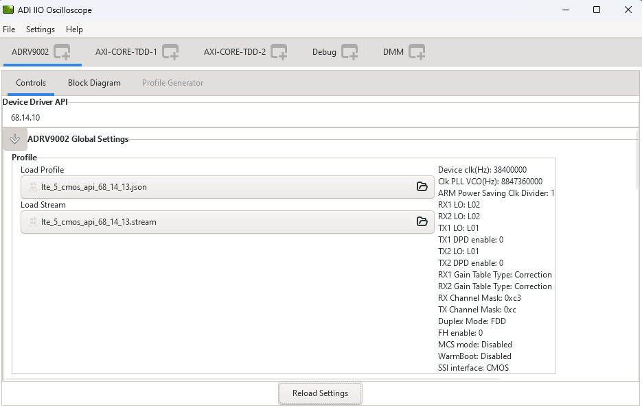
Load Profile: Loads device configuration settings from a JSON file that sets filters, clock rates, and signal paths.
Load Stream: Loads the stream binary file corresponding to the profile. Must be loaded before loading the profile.
Loading Profile and Stream Files
To load the stream and profile configuration:
Click the folder icon next to Load Stream and Load Profile. Loading these files will configure the IIO Oscilloscope automatically, eliminating the need for manual setup.
Navigate to
Program Files > IIO Oscilloscope > lib > osc > filters > adrv9002Select the appropriate profile and stream pair from this directory.
Receive Chain Configuration
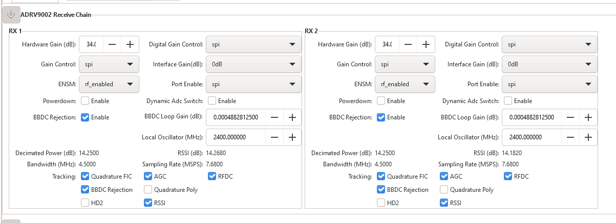
The Receive Chain section provides comprehensive control over the RX signal path for both channels
Signal Path Parameters
Bandwidth(MHz): Displays the Primary Signal Bandwidth of the currently loaded profile. This parameter defines the usable signal bandwidth for the receive path.
Sampling Rate(MSPS):Shows the RX Sample Rate configured in the current profile. This determines the digital sampling frequency for received signals.
Gain Control Settings
Gain Control: - SPI: Manual gain control via software interface - PIN: Hardware pin-controlled gain adjustment - Automatic: Automatic gain control (AGC) mode
Hardware Gain(dB): Controls the RX gain when in SPI or PIN mode. This setting adjusts the analog gain in the receive signal path.
Signal Monitoring
RSSI(dB): Displays the Received Signal Strength Indicator, providing real-time measurement of input signal level.
Decimated Power: Shows the decimated power measurement, useful for signal analysis and monitoring.
Frequency Control
Local Oscillator: Controls the carrier frequency for the receive chain. This sets the center frequency for signal reception.
Warning
If you made a physical loopback between the RX and TX channels, make sure the Local Oscillator value is the same for both channels.
Channel Control
Powerdown: While off disables the receive channel.
Dynamic ADC Switch: Enables dynamic ADC switching functionality for optimized power management and performance.
- ENSM (Enable State Machine):
Selects the operational mode for the Enable State Machine: - Calibrated: Normal operation with calibrations enabled - Primed: Standby mode ready for quick activation - RF Enabled: Full RF operation mode
- Port Enable:
Configures how the port can be enabled: - SPI: Software-controlled port enable - PIN: Hardware pin-controlled port enable
Digital Signal Processing
Digital Gain Control: Selects the digital gain control mode for fine-tuning signal levels in the digital domain.
Interface Gain (dB): Controls the Slicer block gain for digital signal processing optimization.
Tracking Calibrations: Enable/disable various tracking calibration algorithms:
Quadrature FIC: Quadrature frequency image correction
BBDC Rejection: Baseband DC offset rejection
HD2: Second harmonic distortion correction
AGC: Automatic gain control calibration
Quadrature Poly: Quadrature polynomial correction
RSSI: RSSI calibration
RDFC: Receive data formatting correction
Transmit Chain Configuration
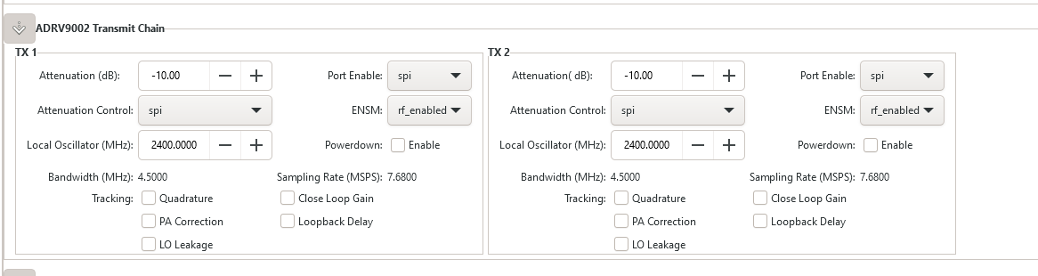
The Transmit Chain section provides control over the TX signal path for both channels.
Signal Path Parameters
Bandwidth (MHz): Displays the Primary Signal Bandwidth for the transmit path as defined in the current profile.
Sampling Rate (MSPS): Shows the TX Sample Rate configured in the current profile, determining the digital sampling frequency for transmitted signals.
Power Control
Attenuation (dB): Controls the TX output power attenuation. Higher values reduce output power.
Attenuation Control Mode: Selects the attenuation control mechanism:
SPI: Software-controlled attenuation
PIN: Hardware pin-controlled attenuation
Bypass: Bypass attenuation control
Channel Control
Powerdown: While off disables the transmit channel, stopping signal transmission and reducing power consumption.
ENSM (Enable State Machine): Configures the transmit channel operational mode similar to the receive chain.
Port Enable: Selects port enable control method (SPI or PIN) for the transmit channel.
Frequency Control
Local Oscillator (MHz): Sets the carrier frequency for signal transmission.
Warning
If you made a physical loopback between the RX and TX channels, make sure the Local Oscillator value is the same for both channels.
Tracking Calibrations: Enable/disable transmit-specific calibration algorithms: - Quadrature: Quadrature correction for TX path - PA Correction: Power amplifier linearity correction - LO Leakage: Local oscillator leakage correction - Close Loop Gain: Closed-loop gain calibration - Loopback Delay: Loopback delay calibration
FPGA Settings
Transmit/DDS
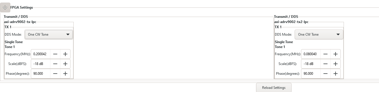
The plugin provides several options on how the transmitted data is generated.
It is possible to either use the built-in two tone Direct Digital Synthesizer (DDS) to transmit a bi-tonal signal on channels I and Q of the DAC. Or it is possible to use the Direct Memory Access (DMA) facility to transmit custom data that you have stored in a file.
This can be achieved by selecting one of the following options listed by the DDS Mode:
One CW Tone
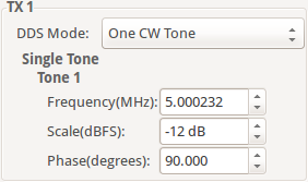
In One CW Tone mode one continuous wave (CW) tone will be outputted. The plugin displays the controls to set the Frequency, Amplitude and Phase for just one tone and makes sure that the amplitude of the other tone is set to 0. The resulting signal will be outputted on the Channel I of the DAC and the exact same signal but with a difference in phase of 90 degrees will be outputted on the Channel Q of the DAC.
Two CW Tone
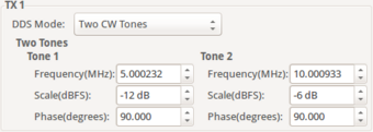
In Two CW Tone mode two continuous wave (CW) tones will be outputted. The plugin displays the controls to set the frequencies F1 and F2, amplitudes A1 and A2, phases P1 and P2 for the two tones. The resulting signal will be outputted on the Channel I of the DAC and the exact same signal but with a difference in phase of 90 degrees will be outputted on the Channel Q of the DAC.
Independent I/Q Control
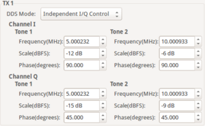
In Independent I/Q Control the plugin displays the controls to set the frequencies, amplitudes and phases for the two tones that will be outputted on channel I and additionally it allows for the two tones that will be outputted on channel Q of the DAC to be configured independently.
Note
Note: The bi-tonal signal (T) is defined as the sum of two tones: T(t) = A1 * sin(2 * p * F1 * t + P1) + A2 * sin(2 * p * F2 * t + P2), where A-amplitude, F-frequency, P-phase of a tone.
DAC Buffer Output
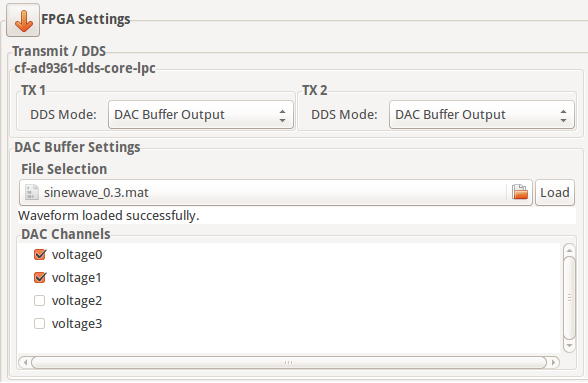
The file selector under the File Selection section is used to locate and choose the desired data file. Under the DAC Channels section the enabled channels will be used to transmit the data stored in the file. To finalize the process, a click on the Load button is required.
Restrictions:
There are two types of files than can be loaded: .txt or .mat. The IIO-Oscilloscope comes with several data files that can be used. If you want to create your own data files please take a look at the Basic IQ Data Files documentation first.
Due to hardware limitation only specific combinations of enabled channels are possible. You can enable a total of 1, 2, 4, etc. channels. If 1 channel is enabled then it can be any of them. If two channels are enabled then channels 0, 1 or channels 2, 3 can be enabled and so on.
Disable
In this mode both DDS and DMA are disabled causing the DAC channels to stop transmitting any data.
Note
Upon pressing Reload Settings button the values will be reloaded with the corresponding driver values. Useful in scenarios where the driver values get changed outside this plugin and a refresh on plugin’s values is needed.
Hint
Some plugin values will be rounded to the nearest value supported by the hardware.
Profile Generator
ADRV9002 device profiles configure the digital filters, analog filters, clock rates, and signal paths. There are two ways to generate profiles:
Using TES (Transceiver Evaluation Software)
The Transceiver Evaluation Software (TES) is a standalone Windows application from Analog Devices dedicated to generating ADRV9002 profiles and stream files. It provides full control over all profile parameters including signal type selection (LTE, DMR, etc.), interface rate configuration, NCO frequency offset, antenna diversity, and frequency hopping settings. TES is used exclusively for profile generation and does not provide data acquisition or device control capabilities.
For a detailed guide, see Profile generation flow using TES.
Using the Integrated Plugin Profile Generator
Both the IIO Oscilloscope and Scopy ADRV9002 plugins include an integrated Profile Generator tab that provides a graphical interface for creating and managing device profiles. This approach allows profile generation within the same tool used for device control and data acquisition.
Warning
The Profile Generator functionality requires the libadrv9002-iio library to be installed. If this external tool is missing, the Profile Generator functionality will be disabled. The library can be obtained from: https://analogdevicesinc.github.io/libadrv9002-iio
More information about this topic can be found in the Scopy ADRV9002 Plugin Documentation.