AD6676
AD6676 Wideband IF Receiver Subsystem Linux device driver.
The AD6676 is a highly integrated IF subsystem that can digitize radio frequency (RF) bands up to 160 MHz in width centered on an intermediate frequency (IF) of 70 MHz to 450 MHz.
Supported Devices
Reference Circuits
Evaluation Boards
Description
This is a Linux industrial I/O (Linux Industrial I/O Subsystem) subsystem driver, targeting RF Transceivers. The industrial I/O subsystem provides a unified framework for drivers for many different types of converters and sensors using a number of different physical interfaces (i2c, spi, etc). See Linux Industrial I/O Subsystem for more information.
Source Code
Status
Files
Function |
File |
|
|---|---|---|
driver |
||
include |
Example Linux Device-Tree Initialization
The AD6676 driver is a spi-bus driver and can currently only be instantiated via device tree.
Required devicetree properties:
compatible: Should always be
ad6676reg: SPI slave select number
Function |
File |
|---|---|
AD6676-EBZ Device Tree |
Device Driver Customization
Devicetree Property |
Description |
|---|---|
adi,adc-frequency-hz |
Initial ADC frequency in Hz |
adi,adc-frequency-fixed-enable |
Prevents ADC frequency changes after initial setup |
adi,use-external-clk-enable |
Use external CLK |
adi,decimation |
Initial decimation rate [12, 16, 24, 32] |
adi,intermediate-frequency-hz |
Initial IF in Hz |
adi,intermediate-frequency-min-hz |
Allowed minimum IF in Hz |
adi,intermediate-frequency-max-hz |
Allowed maximum IF in Hz |
adi,bandwidth-hz |
Initial bandwidth in Hz |
adi,bandwidth-margin-low-mhz |
Initial bandwidth margin low in Hz |
adi,bandwidth-margin-high-mhz |
Initial bandwidth margin high in Hz |
adi,bandwidth-margin-if-mhz |
Initial bandwidth margin IF in Hz |
adi,external-inductance-l-nh |
The inductance of the external inductors in nH |
adi,idac1-fullscale-adjust |
Initial IDAC_FS [64..16] |
adi,shuffler-control |
Initial shuffler control setting |
adi,shuffler-thresh |
Initial shuffler threshold |
adi,jesd-scrambling-enable |
Enables JESD204B link scrambling |
adi,jesd-use-lvds-syncb-enable |
Use LVDS SYNCB |
adi,jesd-powerdown-sysref-enable |
Powerdown SYSREF |
adi,jesd-l-lanes |
Number of JESD204B lanes |
adi,jesd-f-frames-per-multiframe |
Number of frames per multiframe |
adi,spi-3wire-enable |
Enables SPI 3-WIRE mode |
Enabling Linux driver support
Configure kernel with make menuconfig (alternatively use make xconfig or
make qconfig)
Note
The AD6676 driver depends on CONFIG_SPI
Adding Linux driver support
Configure kernel with make menuconfig (alternatively use make xconfig or
make qconfig)
Linux Kernel Configuration
    Device Drivers  --->
    <*>     Industrial I/O support --->
        --- Industrial I/O support
        -*-   Enable ring buffer support within IIO
        -*-     Industrial I/O lock free software ring
        -*-   Enable triggered sampling support

              *** Analog to digital converters ***
        [--snip--]

        <*>   Analog Devices AD9467 AD9643 High-Speed AXI ADC driver

        [--snip--]
Hardware configuration
Driver testing / API
Each and every IIO device, typically a hardware chip, has a device folder under
/sys/bus/iio/devices/iio:deviceX. Where X is the IIO index of the device. Under
every of these directory folders reside a set of files, depending on the
characteristics and features of the hardware device in question. These files
are consistently generalized and documented in the IIO ABI documentation. In
order to determine which IIO deviceX corresponds to which hardware device, the
user can read the name file /sys/bus/iio/devices/iio:deviceX/name. In case
the sequence in which the iio device drivers are loaded/registered is constant,
the numbering is constant and may be known in advance.

root:/> cd /sys/bus/iio/devices/
root:/sys/bus/iio/devices> ls
iio:device0  iio:device1

root:/sys/bus/iio/devices> cd iio:device1

root:/sys/bus/iio/devices/iio:device1# ls -l
drwxr-xr-x 5 root root    0 Jan 22 08:19 .
drwxr-xr-x 4 root root    0 Jan 22 08:19 ..
drwxr-xr-x 2 root root    0 Jan 22 08:19 buffer
-r--r--r-- 1 root root 4096 Jan 22 08:19 dev
-rw-r--r-- 1 root root 4096 Jan 22 08:19 in_voltage_adc_frequency
-rw-r--r-- 1 root root 4096 Jan 22 08:19 in_voltage_bandwidth
-rw-r--r-- 1 root root 4096 Jan 22 08:19 in_voltage_bw_margin_high
-rw-r--r-- 1 root root 4096 Jan 22 08:19 in_voltage_bw_margin_if
-rw-r--r-- 1 root root 4096 Jan 22 08:19 in_voltage_bw_margin_low
-rw-r--r-- 1 root root 4096 Jan 22 08:19 in_voltage_hardwaregain
-rw-r--r-- 1 root root 4096 Jan 22 08:19 in_voltage_intermediate_frequency
-rw-r--r-- 1 root root 4096 Jan 22 08:19 in_voltage_sampling_frequency
-rw-r--r-- 1 root root 4096 Jan 22 08:19 in_voltage_scale
-rw-r--r-- 1 root root 4096 Jan 22 08:19 in_voltage_shuffler_control
-r--r--r-- 1 root root 4096 Jan 22 08:19 in_voltage_shuffler_control_available
-rw-r--r-- 1 root root 4096 Jan 22 08:19 in_voltage_shuffler_thresh
-r--r--r-- 1 root root 4096 Jan 22 08:19 in_voltage_shuffler_thresh_available
-rw-r--r-- 1 root root 4096 Jan 22 08:19 in_voltage_test_mode
-r--r--r-- 1 root root 4096 Jan 22 08:19 in_voltage_test_mode_available
-r--r--r-- 1 root root 4096 Jan 22 08:19 name
drwxr-xr-x 2 root root    0 Jan 22 08:19 power
drwxr-xr-x 2 root root    0 Jan 22 08:19 scan_elements
lrwxrwxrwx 1 root root    0 Jan 22 08:19 subsystem -> ../../../../../bus/iio
-rw-r--r-- 1 root root 4096 Jan 22 08:19 uevent

root:/sys/bus/iio/devices/iio:device1#
Show device name
root:/sys/bus/iio/devices/iio:device1> cat name
axi-ad6676-hpc
ADC frequency FADC (in_voltage_adc_frequency)
The clock frequency of the ADC. Maximizing the clock frequency is helpful when the IF or bandwidth are high. A lower clock frequency reduces power consumption and is appropriate for low IFs and narrow bandwidths.
Range using external synthesizer [2.0,3.2] GHz in Hz Range using internal synthesizer [2.925,3.2] GHz in Hz
root@analog:/sys/bus/iio/devices/iio:device1# cat in_voltage_adc_frequency
3200000000
root@analog:/sys/bus/iio/devices/iio:device1# echo 3000000000 > in_voltage_adc_frequency
-bash: echo: write error: Invalid argument
Tip
If writing this attribute returns Invalid argument (-EINVAL) this means
that the underlying HDL or Hardware’s JESD204B Core and Gigabit Transceiver
(GT) doesn’t support changing the JESD204B Lane Rate.
Complex IQ Data Rate (in_voltage_sampling_frequency)
The complex (I/Q) data rate in SPS. The AD6676 supports decimation factors (DFs) of 12, 16, 24 and 32. The complex (I/Q) data rate at the JESD204B outputs is FADC / DF.
In case the underlying HDL or Hardware’s JESD204B Core and Gigabit Transceiver (GT) support arbitrary JESD204B Lane Rates. This attribute can be writable. And it will select the appropriate AD6676 supported DFs.
root@analog:/sys/bus/iio/devices/iio:device1# cat in_voltage_sampling_frequency
200000000
IF intermediate frequency (in_voltage_intermediate_frequency)
The IF (intermediate frequency) to which the ADC is tuned. The AD6676 supports IFs from 70 to 450 MHz provided the external inductors are chosen appropriately. Since the AD6676-EBZ by default includes a pair of 19-nH inductors soldered to the evaluation board, the IF range allowed is less than the full range supported by the AD6676.
Tip
Please see paragraph Lext Selection in the datasheet: Maximum External Inductor Value as a Function of IF Frequency
The min/max values the device driver accepts can be set via following devicetree attributes:
adi,intermediate-frequency-min-hz = <150000000>;
adi,intermediate-frequency-max-hz = <450000000>;
Since the tuning accuracy is finite - reading back this value allows the user to determine the offset.
root@analog:/sys/bus/iio/devices/iio:device1# echo 200000000 > in_voltage_intermediate_frequency
root@analog:/sys/bus/iio/devices/iio:device1# cat in_voltage_intermediate_frequency
200000000

root@analog:/sys/bus/iio/devices/iio:device1# echo 199000000 > in_voltage_intermediate_frequency
root@analog:/sys/bus/iio/devices/iio:device1# cat in_voltage_intermediate_frequency
199218750
Bandwidth (in_voltage_bandwidth)
The bandwidth of the ADC. Since the AD6676 uses delta-sigma technology, the available bandwidth is a relatively small fraction of the ADC clock rate and the AD6676 achieves the lowest noise and distortion when the bandwidth is small.
The allowed range is between [0.005,0.05]*FADC in Hz
root@analog:/sys/bus/iio/devices/iio:device1# echo 100000000 > in_voltage_bandwidth
root@analog:/sys/bus/iio/devices/iio:device1# cat in_voltage_bandwidth
100000000
Bandwidth Margins (in_voltage_bw_margin_[low|high])
Lower (in_voltage_bw_margin_low) and upper (in_voltage_bw_margin_high) bandwidth margins for the noise-shaping profile of the ADC.
Typical values are 5 MHz, but the user may want to increase these margins in wideband operation in order to optimize the noise profile of the ADC.
Typical range [0,30] MHz in MHz
root@analog:/sys/bus/iio/devices/iio:device1# echo 5 > in_voltage_bw_margin_low
root@analog:/sys/bus/iio/devices/iio:device1# cat in_voltage_bw_margin_low
5
Bandwidth Margin IF (in_voltage_bw_margin_if)
Displacement of the resonance frequency (F1Shift) of the first resonator within the ADC from band-center. Typically 0 is appropriate, but in the widest bandwidth modes positive shifts can be used to reduce the noise density near the upper edge of the passband.
Typical range [-30,30] MHz in MHz
root@analog:/sys/bus/iio/devices/iio:device1# echo -1 > in_voltage_bw_margin_if
root@analog:/sys/bus/iio/devices/iio:device1# cat in_voltage_bw_margin_if
-1
Full-Scale (in_voltage_scale)
One of the convenient features of the AD6676 is that the full-scale of its ADC is relatively small and adjustable over a 12-dB range [1.00 .. 0.25] The dynamic range of the ADC is highest at the maximum full-scale setting but the noise figure of the system is lowest at the minimum full-scale setting.
Writing a value of 0.5 to this device attribute lowers the PIN_0dBFS by 6 dB. Likewise writing a value of 0.25 to this device attribute lowers the PIN_0dBFS by 12 dB.
root@analog:/sys/bus/iio/devices/iio:device1# cat in_voltage_scale
1.000000
root@analog:/sys/bus/iio/devices/iio:device1# echo 0.25 > in_voltage_scale
root@analog:/sys/bus/iio/devices/iio:device1# cat in_voltage_scale
0.250000
Attenuation Control (in_voltage_hardwaregain)
The AD6676 contains a 50-ohm input attenuator programmable in 1-dB steps. Use this device attribute to set the attenuator’s attenuation. The dynamic range of the system increases somewhat with moderate attenuation settings of 6-12 dB, at the expense of an increased noise figure.
The range is from 0 to -27.00 dB in 1dB steps. The nomenclature used here is gain instead of attenuation, so all values are expressed negative.
root@analog:/sys/bus/iio/devices/iio:device1# echo -10.00 > in_voltage_hardwaregain

root@analog:/sys/bus/iio/devices/iio:device1# cat in_voltage_hardwaregain
-10.000000 dB
Shuffle Control (in_voltage_shuffler_control)
The AD6676 includes dynamic reordering of the comparators within the ADC in
order to break up the spurious tones and distortion products associated with a
fixed ordering. The Shuffle Control device attribute allows the user to
experiment with different shuffling rates. The fadc option (Shuffle every 1)
reorders the comparators on every clock cycle with 50% probability. This shuffle
scheme is able to randomize deterministic spurs but tends to increase the noise
density and creates FADC/32 shuffle humps in the output spectrum. Similarly,
the fadc/2 fadc/3 fadc/4 (Shuffle every 2,3,4) options reorder the
comparators every n clock cycles with 50% probability. Using a high value of n
decreases the noise degradation at the expense of less effective randomization
and FADC/(32*n) shuffle humps that are closer to the main carrier. Fast
shuffling can be disabled by selecting the disable option.
root@analog:/sys/bus/iio/devices/iio:device1# cat in_voltage_shuffler_control_available
disable fadc fadc/2 fadc/3 fadc/4
root@analog:/sys/bus/iio/devices/iio:device1# cat in_voltage_shuffler_control
fadc
root@analog:/sys/bus/iio/devices/iio:device1# echo disable > in_voltage_shuffler_control
root@analog:/sys/bus/iio/devices/iio:device1# cat in_voltage_shuffler_control
disable
Shuffle Threshold (in_voltage_shuffler_thresh)
In order to obtain the spur-reduction benefits of shuffling at large signal levels while retaining the low noise of not shuffling when the signal is small, the AD6676 supports dynamic shuffle control via the Shuffle Threshold attribute. Shuffling is disabled if the raw ADC output is below the specified threshold for ~5000 clock cycles. A threshold of zero implies that shuffling is always enabled.
The supported range is from 0..8
root@analog:/sys/bus/iio/devices/iio:device1# cat in_voltage_shuffler_thresh_available
0 1 2 3 4 5 6 7 8
root@analog:/sys/bus/iio/devices/iio:device1# cat in_voltage_shuffler_thresh
5
root@analog:/sys/bus/iio/devices/iio:device1# echo 4 > in_voltage_shuffler_thresh
root@analog:/sys/bus/iio/devices/iio:device1# cat in_voltage_shuffler_thresh
4
Test Modes (in_voltage_test_mode)
Interface test modes supported by the AD6676.
root@analog:/sys/bus/iio/devices/iio:device1# cat in_voltage_test_mode_available
off checkerboard one_zero_toggle pn23 pn9 rep_user_pat sing_user_pat ramp mod_rpat jspat jtspat

root@analog:/sys/bus/iio/devices/iio:device1# echo ramp > in_voltage_test_mode
root@analog:/sys/bus/iio/devices/iio:device1# cat in_voltage_test_mode
ramp
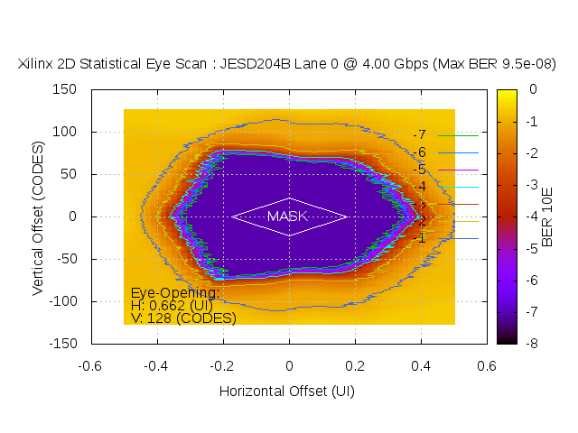
JESD204B Interface Testing
Below Eyes were captured on a Xilinx ZC706 after > 4 hours of operation: