AD9361
AD9361 Device Driver Customization.
Note
There are configuration options that must be set properly. Some others allow you to set defaults, but can be changed anytime later using the driver API. But most of these options don’t need to be changed at all.
If unsure please see the manual or don’t change!
The Linux platform allows you to examine and determine optimal settings for your target application: See here: AD936X Advanced Plugin
Linux/No-OS device driver comparison
Linux Device Tree Attribute |
No-OS AD9361_ParamInit structure member |
Description |
||
|---|---|---|---|---|
Base Configuration |
||||
adi,2rx-2tx-mode-enable |
two_rx_two_tx_mode_enable |
Use 2Rx2Tx mode - default 1Rx1Tx (AD9364 must clear this) |
||
adi,1rx-1tx-mode-use-rx-num |
one_rx_one_tx_mode_use_rx_num |
Valid only in 1Rx1Tx mode for AD9361 and AD9363, Selects which RX channel is used |
||
adi,1rx-1tx-mode-use-tx-num |
one_rx_one_tx_mode_use_tx_num |
Valid only in 1Rx1Tx mode for AD9361 and AD9363, Selects which TX channel is used |
||
adi,frequency-division-duplex-mode-enable |
frequency_division_duplex_mode_enable |
Use FDD mode - default TDD |
||
adi,tdd-use-dual-synth-mode-enable |
tdd_use_dual_synth_mode_enable |
In TDD mode use Dual Synth mode - default only one Synth is enabled |
||
adi,tdd-skip-vco-cal-enable |
tdd_skip_vco_cal_enable |
Option to skip VCO cal in TDD mode when moving from TX/RX to Alert |
||
ENSM Control |
||||
adi,ensm-enable-pin-pulse-mode-enable |
ensm_enable_pin_pulse_mode_enable |
ENSM control Pins (ENABLE/TXNRX) use Pulse mode - default Level Mode |
||
adi,ensm-enable-txnrx-control-enable |
ensm_enable_txnrx_control_enable |
ENSM control Pins (ENABLE/TXNRX) control ENSM state - default SPI writes |
||
adi,frequency-division-duplex-independent-mode-enable |
frequency_division_duplex_independent_mode_enable |
Use independent FDD mode - allows individual control over RX and TX (Pin Mode Only) |
||
LO Control |
||||
adi,rx-synthesizer-frequency-hz |
rx_synthesizer_frequency_hz |
RX LO power-up Frequency in Hz |
||
adi,tx-synthesizer-frequency-hz |
tx_synthesizer_frequency_hz |
TX LO power-up Frequency in Hz |
||
adi,tx-fastlock-delay-ns |
tx_fastlock_delay_ns |
TX fastlock delay in ns |
||
adi,rx-fastlock-delay-ns |
rx_fastlock_delay_ns |
RX fastlock delay in ns |
||
adi,rx-fastlock-pincontrol-enable |
rx_fastlock_pincontrol_enable |
RX fastlock pin control enable |
||
adi,tx-fastlock-pincontrol-enable |
tx_fastlock_pincontrol_enable |
RX fastlock pin control enable |
||
adi,trx-synthesizer-target-fref-overwrite-hz |
trx_synthesizer_target_fref_overwrite_hz |
This allows forcing a lower F_REF window (worse phase noise, better fractional spurs) |
||
adi,external-tx-lo-enable |
external_tx_lo_enable |
Enables external LO for TX |
||
adi,external-rx-lo-enable |
external_rx_lo_enable |
Enables external LO for RX |
||
Rate & BW Control |
||||
adi,rx-path-clock-frequencies |
rx_path_clock_frequencies[6] |
RX Path Frequencies in Hz (see also Here |
||
adi,tx-path-clock-frequencies |
tx_path_clock_frequencies[6] |
TX Path Frequencies in Hz (see also Here |
||
adi,rf-rx-bandwidth-hz |
rf_rx_bandwidth_hz |
RX RF Bandwidth power-up setting |
||
adi,rf-tx-bandwidth-hz |
rf_tx_bandwidth_hz |
TX RF Bandwidth power-up setting |
||
RF Port Control |
||||
adi,rx-rf-port-input-select |
rx_rf_port_input_select |
Please see Here |
||
adi,tx-rf-port-input-select |
tx_rf_port_input_select |
|||
adi,rx1-rx2-phase-inversion-enable |
rx1rx2_phase_inversion_en |
If enabled RX1 and RX2 are phase aligned |
||
TX Attenuation Control |
||||
adi,tx-attenuation-mdB |
tx_attenuation_mdB |
TX power-up attenuation in milli dB |
||
adi,update-tx-gain-in-alert-enable |
update_tx_gain_in_alert_enable |
in TDD mode disable immediate TX Gain update and wait until ENSM moves to Alert |
||
Reference Clock Control |
||||
adi,xo-disable-use-ext-refclk-enable |
xo_disable_use_ext_refclk_enable |
Disable XO use Ext CLK into XTAL_N - default XO into XTAL |
||
adi,dcxo-coarse-and-fine-tune |
dcxo_coarse_and_fine_tune[2] |
DCXO Fine and Coarse Tune |
||
RX DC/QEC tracking Control |
||||
adi,dc-offset-tracking-update-event-mask |
dc_offset_tracking_update_event_mask |
BIT(0) Apply a new tracking word when a gain change occurs. BIT(1) Apply a new tracking word when the received signal is less than the SOI Threshold. BIT(2) Apply a new tracking word after the device exits the receive state |
||
adi,dc-offset-attenuation-high-range |
dc_offset_attenuation_high_range |
RX LO > 4 GHz: These bits control the attenuator for the initialization and tracking RF DC offset calibrations. The integrated data shifts by this twos complement value and ranges from -16 to +15. |
||
adi,dc-offset-attenuation-low-range |
dc_offset_attenuation_low_range |
RX LO < 4 GHz: These bits control the attenuator for the initialization and tracking RF DC offset calibrations. The integrated data shifts by this twos complement value and ranges from -16 to +15. |
||
adi,dc-offset-count-high-range |
dc_offset_count_high_range |
RX LO > 4 GHz: This value affects both RF DC offset initialization and tracking and it sets the number of integrated samples and the loop gain. The number of samples equals 256 × RF DC Offset Count[7:0] in ClkRF cycles. Increasing this value increases loop gain. |
||
adi,dc-offset-count-low-range |
dc_offset_count_low_range |
RX LO < 4 GHz: This value affects both RF DC offset initialization and tracking and it sets the number of integrated samples and the loop gain. The number of samples equals 256 × RF DC Offset Count[7:0] in ClkRF cycles. Increasing this value increases loop gain. |
||
adi,qec-tracking-slow-mode-enable |
qec_tracking_slow_mode_enable |
Improved RX QEC tracking in case signal of interest is close to DC/LO |
||
Gain Control |
||||
adi,split-gain-table-mode-enable |
split_gain_table_mode_enable |
Enable Split Gain Table Mode - default Full Table |
||
adi,gc-rx1-mode |
gc_rx1_mode |
RX1 Gain control operation: Manual gain (0); Fast attack AGC (1); Slow attack AGC (2); Hybrid AGC (3). See register 0x0FA, bits [D4], [D1:D0]. |
||
adi,gc-rx2-mode |
gc_rx2_mode |
RX2 Gain control operation: Manual gain (0); Fast attack AGC (1); Slow attack AGC (2); Hybrid AGC (3). See register 0x0FA, bits [D4], [D3:D2]. |
||
adi,gc-adc-large-overload-thresh |
gc_adc_large_overload_thresh |
This attribute sets the large ADC overload. See register 0x105. |
||
adi,gc-adc-ovr-sample-size |
gc_adc_ovr_sample_size |
This attribute equals the number of ADC output samples used to determine an ADC overload. See register 0x0FC, bits [D2:D0]. This data is processed by the driver. |
||
adi,gc-adc-small-overload-thresh |
gc_adc_small_overload_thresh |
This attribute sets the small ADC overload. See register 0x104. |
||
adi,gc-dec-pow-measurement-duration |
gc_dec_pow_measurement_duration |
The power measurement duration used by the gain control algorithm. See register 0x15C, bits [D3:D0]. This data is processed by the driver. |
||
adi,gc-use-rx-fir-out-for-dec-pwr-meas-enable |
gc_use_rx_fir_out_for_dec_pwr_meas_enable |
Set to use the RX FIR output for power measurements. Default/Clear to use the HB1 output. See register 0x15C, bits [D6]. |
||
adi,gc-dig-gain-enable |
gc_dig_gain_enable |
This attribute is used in split table mode to enable the digital gain pointer. See register 0x0FB, bit D2. |
||
adi,gc-lmt-overload-high-thresh |
gc_lmt_overload_high_thresh |
This attribute sets the large LMT overload threshold. See register 0x108. This data is processed by the driver. |
||
adi,gc-lmt-overload-low-thresh |
gc_lmt_overload_low_thresh |
This attribute sets the small LMT overload threshold. See register 0x107. This data is processed by the driver. |
||
adi,gc-low-power-thresh |
gc_low_power_thresh |
This threshold is used by the fast AGC to determine if the gain should be increased. It can also be used to trigger a CTRL_OUT signal transition in MGC mode. See register 0x114, bits [D6:D0]. This data is processed by the driver. |
||
adi,gc-max-dig-gain |
gc_max_dig_gain |
This attribute equals the maximum allowable digital gain, and applies to all gain control modes. See register 0x100, bits [D4:D0]. |
||
Gain MGC Control |
||||
adi,mgc-dec-gain-step |
mgc_dec_gain_step |
This attribute applies if the CTRL_IN signals control gain. The gain index decreases by this value when certain CTRL_IN signals transition high. See register 0x0FE, bits [D7:D5]. This data is processed by the driver. |
||
adi,mgc-inc-gain-step |
mgc_inc_gain_step |
This attribute applies if the CTRL_IN signals control gain. The gain index increases by this value when certain CTRL_IN signals transition high. See register 0x0FC, bits [D7:D5]. This data is processed by the driver. |
||
adi,mgc-rx1-ctrl-inp-enable |
mgc_rx1_ctrl_inp_enable |
If this attribute is clear, SPI writes change the RX1 gain. When this attribute is set, control input pins control the gain. See register 0x0FB, bit [D0]. |
||
adi,mgc-rx2-ctrl-inp-enable |
mgc_rx2_ctrl_inp_enable |
If this attribute is clear, SPI writes change the RX2 gain. When this attribute is set, control input pins control the gain. See register 0x0FB, bit [D1]. |
||
adi,mgc-split-table-ctrl-inp-gain-mode |
mgc_split_table_ctrl_inp_gain_mode |
AGC determine this (0); Only in LPF(1); Only in LMT (2). See register 0x0FC, bits [D4], [D3]. |
||
Gain AGC Control |
||||
adi,agc-adc-large-overload-exceed-counter |
agc_adc_large_overload_exceed_counter |
This counter specifies the number of large ADC overloads that must occur before the gain will decrease by the large ADC overload gain step. See register 0x122, bits [D7:D4]. |
||
adi,agc-adc-large-overload-inc-steps |
agc_adc_large_overload_inc_steps |
This attribute applies to AGC and determine how much the gain changes for large LPF in split tablemode or the large LMT and large ADC overloads in full table mode. See register 0x106, bits [D3:D0] (Name is misleading should be dec-steps ) |
||
adi,agc-adc-lmt-small-overload-prevent-gain-inc-enable |
agc_adc_lmt_small_overload_prevent_gain_inc_enable |
This attribute set the slow AGC inner low window threshold. See register 0x120, bits [D6:D0]. |
||
adi,agc-adc-small-overload-exceed-counter |
agc_adc_small_overload_exceed_counter |
This counter specifies the number of small ADC overloads that must occur to prevent a gain increase. See register 0x122, bits [D3:D0]. |
||
adi,agc-attack-delay-extra-margin-us |
agc_attack_delay_extra_margin_us |
The AGC Attack Delay prevents the AGC from starting its algorithm until the receive path has settled. The delay counter starts when the ENSM enters the Rx state. See register 0x022, bits [D5:D0]. This data is processed by the driver. |
||
adi,agc-dig-gain-step-size |
agc_dig_gain_step_size |
If digital saturation occurs, digital gain reduces by this value. See register 0x100, bits [D7:D5]. |
||
adi,agc-dig-saturation-exceed-counter |
agc_dig_saturation_exceed_counter |
This counter specifies the number of digital saturation events that much occur to prevent a gain increase. See register 0x128, bits [D3:D0]. |
||
adi,agc-immed-gain-change-if-large-adc-overload-enable |
agc_immed_gain_change_if_large_adc_overload_enable |
Set this attribute to allow large ADC overload to reduce gain immediately. See register 0x123, bit D3. |
||
adi,agc-immed-gain-change-if-large-lmt-overload-enable |
agc_immed_gain_change_if_large_lmt_overload_enable |
Set this attribute to allow large LMT overloads to reduce gain immediately. See register 0x123, bit D7. |
||
adi,agc-inner-thresh-high |
agc_inner_thresh_high |
Applies to AGC. This attribute specifies the fast AGC lock level or specifies the slow AGC inner high threshold. Resolution is −1 dBFS/LSB. See register 0x101 [D6:D0]). |
||
adi,agc-inner-thresh-high-dec-steps |
agc_inner_thresh_high_dec_steps |
This attribute sets the gain decrease amount when the inner high threshold is exceeded. See register 0x123, bits [D6:D4]. |
||
adi,agc-inner-thresh-low |
agc_inner_thresh_low |
This attribute sets the slow AGC inner low window threshold. See register 0x120, bits [D6:D0]. |
||
adi,agc-inner-thresh-low-inc-steps |
agc_inner_thresh_low_inc_steps |
This attribute sets the increase amount used when the gain goes under the inner low threshold. See register 0x123, bits [D2:D0]. |
||
adi,agc-dig-sat-ovrg-enable |
agc_dig_sat_ovrg_enable |
Applies to the fast AGC and full gain table. When clear, digital saturation does not cause a gain decrease. When set, digital saturation will cause a gain decrease. See register 0x101, bit D7. |
||
adi,agc-lmt-overload-large-exceed-counter |
agc_lmt_overload_large_exceed_counter |
This counter specifies the number of large LMT overloads that must occur before gain decreases by the LMT Gain Step. See register 0x121, bits [D7:D4]. |
||
adi,agc-lmt-overload-large-inc-steps |
agc_lmt_overload_large_inc_steps |
This attribute determines how much the gain changes for large LMT in split tablemode or the small ADC overload for the full table. See register 0x103, bits [D4:D2]. |
||
adi,agc-lmt-overload-small-exceed-counter |
agc_lmt_overload_small_exceed_counter |
This counter specifies the number of small LMT overloads that much occur to prevent a gain increase. See register 0x121, bits [D3:D0]. |
||
adi,agc-outer-thresh-high |
agc_outer_thresh_high |
The outer high threshold equals the inner high threshold plus this value. See register 0x129, bits [D7:D4]. This data is processed by the driver. |
||
adi,agc-outer-thresh-high-dec-steps |
agc_outer_thresh_high_dec_steps |
The slow AGC changes gain by this amount when the outer high threshold is exceeded. See register 0x12A, bits [D7:D4]. |
||
adi,agc-outer-thresh-low |
agc_outer_thresh_low |
The outer low threshold equals the inner low threshold plus this value. See register 0x129, bits [D3:D0]. This data is processed by the driver. |
||
adi,agc-outer-thresh-low-inc-steps |
agc_outer_thresh_low_inc_steps |
The slow AGC changes gain by this amount when the outer low threshold is exceeded. See register 0x12A, bits [D3:D0]. |
||
adi,agc-sync-for-gain-counter-enable |
agc_sync_for_gain_counter_enable |
If this attribute is set, CTRL_IN2 transitioning high resets the counter.See register 0x128, bit D4. |
||
Fast AGC |
||||
adi,fagc-dec-pow-measurement-duration |
fagc_dec_pow_measuremnt_duration |
The power measurement duration used by the gain control algorithm. See register 0x15C, bits [D3:D0]. This data is processed by the driver. |
||
adi,fagc-state-wait-time-ns |
fagc_state_wait_time_ns |
The fast AGC delays moving from State 1 to State 2 until no peak overloads are detected for the value of this counter; measured in ClkRF cycles. See register 0x117, bits [D4:D0]. This data is processed by the driver. |
||
adi,fagc-adc-large-overload-inc-steps |
f_agc_large_overload_inc_steps |
Fast Attack Only. Decrement Step Size for: Small LPF Gain Change / Full Table Case #2 <2:0>. See register 0x106, bits [D4:D6] (Name is misleading should be dec-steps!) |
||
Fast AGC - Low Power |
||||
adi,fagc-allow-agc-gain-increase-enable |
fagc_allow_agc_gain_increase |
Setting this attribute allows the fast AGC to increase the gain while optimizing the gain index. Clearing it prevents the gain from increasing in any condition. See register 0x110, bit D0. |
||
adi,fagc-lp-thresh-increment-time |
fagc_lp_thresh_increment_time |
This attribute sets the time that the signal power must remain below the Low Power Threshold before the fast AGC will change gain. Also can be used by the MGC. See register 0x11B, bits [D7:D0]. |
||
adi,fagc-lp-thresh-increment-steps |
fagc_lp_thresh_increment_steps |
The Fast AGC will increase the gain index by this amount if signal power decreases below the Low Power Threshold and only if the Enable Incr Gain is enabled. See register 0x117, bits [D7:D5]. This data is processed by the driver. |
||
Fast AGC - Lock Level (Lock Level is set via slow AGC inner high threshold) |
||||
adi,fagc-lock-level-lmt-gain-increase-enable |
fagc_lock_level_lmt_gain_increase_en |
Set this attribute to allow the AGC to use LMT gain if the gain index needs to increase when moving to the AGC Lock Level. See register 0x111, bit D6. |
||
adi,fagc-lock-level-gain-increase-upper-limit |
fagc_lock_level_gain_increase_upper_limit |
This attribute sets the maximum gain index increase that the fast AGC can use for the lock level adjustment. See register 0x118, bits [D5:D0]. |
||
Fast AGC - Peak Detectors and Final Settling |
||||
adi,fagc-lpf-final-settling-steps |
fagc_lpf_final_settling_steps |
This attribute sets the reduction to the gain index if a large LMT or large ADC overload occurs after Lock Level but before fast AGC state 5. If the number of overloads exceeds the Final Overrange Count (fagc_final_overrange_count), the AGC algorithm restarts. Depending on various conditions if a split table is used, the gain may reduce in in the LPF or the LMT (fagc_lmt_final_settling_steps). See register 0x112, bits [D7:D6]. |
||
adi,fagc-lmt-final-settling-steps |
fagc_lmt_final_settling_steps |
Post Lock Level Step for LMT Table. See register 0x113, bits [D7:D6]. |
||
adi,fagc-final-overrange-count |
fagc_final_overrange_count |
Final Overrange Count. See register 0x116, bits [D7:D5]. |
||
Fast AGC - Final Power Test |
||||
adi,fagc-gain-increase-after-gain-lock-enable |
fagc_gain_increase_after_gain_lock_en |
Set this attribute to allow gain increases after the gain has locked but before State 5. Signal power must be lower than the low power threshold for longer than the increment time duration register. See register 0x110, bit D7. |
||
Fast AGC - Unlocking the Gain |
||||
adi,fagc-gain-index-type-after-exit-rx-mode |
fagc_gain_index_type_after_exit_rx_mode |
MAX Gain (0); Optimized Gain (1); Set Gain (2). See register 0x110, bits D4,D2. This data is processed by the driver. |
||
adi,fagc-use-last-lock-level-for-set-gain-enable |
fagc_use_last_lock_level_for_set_gain_en |
Set this attribute to use the last gain index of the previous frame for set gain. Clear to use the first gain index of the previous frame. See register 0x111, bit D7. |
||
adi,fagc-rst-gla-stronger-sig-thresh-exceeded-enable |
fagc_rst_gla_stronger_sig_thresh_exceeded_en |
If this attribute is set and the fast AGC is in State 5, the gain will not change even if the signal power increase by more than the Stronger Signal Threshold. See register 0x115, bit D7. |
||
adi,fagc-optimized-gain-offset |
fagc_optimized_gain_offset |
The offset added to the last gain lock level of the previous frame. The result is the optimize gain index. See register 0x116, bits [D3:D0]. |
||
adi,fagc-rst-gla-stronger-sig-thresh-above-ll |
fagc_rst_gla_stronger_sig_thresh_above_ll |
If the signal power increases by this threshold and the signal power remains at this level or higher for a duration that is twice the Gain Lock Exit Count, the gain may unlock, depending on other AGC configuration bits. See register 0x113, bits [D5:D0]. |
||
adi,fagc-rst-gla-engergy-lost-sig-thresh-exceeded-enable |
fagc_rst_gla_engergy_lost_sig_thresh_exceeded_en |
If this attribute is set and the fast AGC is in State 5, the gain will not change even if the average signal power decreases more than the Energy Lost Threshold register. See register 0x110, bit D3. |
||
adi,fagc-rst-gla-engergy-lost-goto-optim-gain-enable |
fagc_rst_gla_engergy_lost_goto_optim_gain_en |
If this attribute is set and the fast AGC is in State 5, the gain index will go to the optimize gain value if an energy lost state occurs or when the EN_AGC signal goes high. See register 0x110, bit D6. |
||
adi,fagc-rst-gla-engergy-lost-sig-thresh-below-ll |
fagc_rst_gla_engergy_lost_sig_thresh_below_ll |
If the signal power decreases by this threshold and the signal power remains at this level or lower for a duration that is twice the Gain Lock Exit Count, the gain may unlock, depending on other AGC configuration bits. See register 0x112, bits [D5:D0]. |
||
adi,fagc-energy-lost-stronger-sig-gain-lock-exit-cnt |
fagc_energy_lost_stronger_sig_gain_lock_exit_cnt |
Gain Lock Exit Count. See register 0x119, bits [D5:D0]. |
||
adi,fagc-rst-gla-large-adc-overload-enable |
fagc_rst_gla_large_adc_overload_en |
Unlock gain if ADC Ovrg, Lg ADC or LMT Ovrg. See register 0x110, bit D1 and register 0x114, bit D7. This data is processed by the driver. |
||
adi,fagc-rst-gla-large-lmt-overload-enable |
fagc_rst_gla_large_lmt_overload_en |
Unlock Gain if Lg ADC or LMT Ovrg. See register 0x110, bit D1. |
||
adi,fagc-rst-gla-en-agc-pulled-high-enable |
fagc_rst_gla_en_agc_pulled_high_en |
See fagc_rst_gla_if_en_agc_pulled_high_mode. This data is processed by the driver. |
||
adi,fagc-rst-gla-if-en-agc-pulled-high-mode |
fagc_rst_gla_if_en_agc_pulled_high_mode |
MAX Gain (0); Optimized Gain (1); Set Gain (2), No gain change. See registers 0x110, 0x111 |
||
adi,fagc-power-measurement-duration-in-state5 |
fagc_power_measurement_duration_in_state5 |
The power measurement duration used by the gain control algorithm for State 5 (gain lock) - fast AGC. See register 0x109, bit D7 and 0x10a, bits [D7:D5]. |
||
RSSI Control |
||||
adi,rssi-delay |
rssi_delay |
Please see Here |
||
adi,rssi-duration |
rssi_duration |
|||
adi,rssi-restart-mode |
rssi_restart_mode |
|||
adi,rssi-unit-is-rx-samples-enable |
rssi_unit_is_rx_samples_enable |
|||
adi,rssi-wait |
rssi_wait |
|||
adi,rssi-gain-step-lna-error-table |
RSSI Gain Step LNA error table values |
|||
adi,rssi-gain-step-mixer-error-table |
RSSI Gain Step Mixer error table values |
|||
adi,rssi-gain-step-calibration-register-values |
Maximum LNA Gain, LNA Gain difference word for Index 0, LNA Gain difference word for Index 1, LNA Gain difference word for Index 2, LNA Gain difference word for Index 3 |
|||
Aux ADC Control |
||||
adi,aux-adc-decimation |
aux_adc_decimation |
This sets the AuxADC decimation, See register 0x01D, bits [D3:D1]. This data is processed by the driver. |
||
adi,aux-adc-rate |
aux_adc_rate |
This sets the AuxADC clock frequency in Hz. See register 0x01C, bits [D5:D0]. This data is processed by the driver. |
||
Temperature Sensor Control |
||||
adi,temp-sense-decimation |
temp_sense_decimation |
Decimation of the AuxADC used to derive the temperature. This data is processed by the driver. |
||
adi,temp-sense-measurement-interval-ms |
temp_sense_measurement_interval_ms |
Measurement interval in ms. This data is processed by the driver. |
||
adi,temp-sense-offset-signed |
temp_sense_offset_signed |
Offset in signed deg. C, range -128…127 |
||
adi,temp-sense-periodic-measurement-enable |
temp_sense_periodic_measurement_enable |
Enables periodic measurement |
||
Aux DAC Control |
||||
adi,aux-dac-manual-mode-enable |
aux_dac_manual_mode_enable |
If enabled the Aux DAC doesn’t slave the ENSM |
||
adi,aux-dac1-default-value-mV |
aux_dac1_default_value_mV |
DAC1 default voltage in mV |
||
adi,aux-dac1-active-in-rx-enable |
aux_dac1_active_in_rx_enable |
If enabled DAC is active in RX mode |
||
adi,aux-dac1-active-in-tx-enable |
aux_dac1_active_in_tx_enable |
If enabled DAC is active in TX mode |
||
adi,aux-dac1-active-in-alert-enable |
aux_dac1_active_in_alert_enable |
If enabled DAC is active in ALERT mode |
||
adi,aux-dac1-rx-delay-us |
aux_dac1_rx_delay_us |
RX delay in us |
||
adi,aux-dac1-tx-delay-us |
aux_dac1_tx_delay_us |
TX delay in us |
||
adi,aux-dac2-default-value-mV |
aux_dac2_default_value_mV |
DAC2 default voltage in mV |
||
adi,aux-dac2-active-in-rx-enable |
aux_dac2_active_in_rx_enable |
If enabled DAC is active in RX mode |
||
adi,aux-dac2-active-in-tx-enable |
aux_dac2_active_in_tx_enable |
If enabled DAC is active in TX mode |
||
adi,aux-dac2-active-in-alert-enable |
aux_dac2_active_in_alert_enable |
If enabled DAC is active in ALERT mode |
||
adi,aux-dac2-rx-delay-us |
aux_dac2_rx_delay_us |
RX delay in us |
||
adi,aux-dac2-tx-delay-us |
aux_dac2_tx_delay_us |
TX delay in us |
||
GPO Control |
||||
adi,gpo-manual-mode-enable |
Enables GPO manual mode, this will conflict with automatic ENSM slave and eLNA mode |
|||
adi,gpo-manual-mode-enable-mask |
Enable bit mask, setting or clearing bits will change the level of the corresponding output. Bit0 -> GPO, Bit1 -> GPO1, Bit2 -> GPO2, Bit3 -> GP03 |
|||
adi,gpo0-inactive-state-high-enable |
gpo0_inactive_state_high_enable |
When clear, the GPOs are logic low in the Sleep, Wait, and Alert States and when set, the GPOs are logic high in the Alert state. |
||
adi,gpo0-slave-rx-enable |
gpo0_slave_rx_enable |
When set this GPO pin change state when the ENSM enters the RX state |
||
adi,gpo0-slave-tx-enable |
gpo0_slave_tx_enable |
When set this GPO pin change state when the ENSM enters the TX state |
||
adi,gpo0-rx-delay-us |
gpo0_rx_delay_us |
This value set the delay from an ENSM state change of Alert to RX to the time that the GPOs change logic level. 1us/LSB with a range from 0 to 255 us. |
||
adi,gpo0-tx-delay-us |
gpo0_tx_delay_us |
This value set the delay from an ENSM state change of Alert to TX to the time that the GPOs change logic level. 1us/LSB with a range from 0 to 255 us. |
||
adi,gpo1-inactive-state-high-enable |
gpo1_inactive_state_high_enable |
When clear, the GPOs are logic low in the Sleep, Wait, and Alert States and when set, the GPOs are logic high in the Alert state. |
||
adi,gpo1-slave-rx-enable |
gpo1_slave_rx_enable |
When set this GPO pin change state when the ENSM enters the RX state |
||
adi,gpo1-slave-tx-enable |
gpo1_slave_tx_enable |
When set this GPO pin change state when the ENSM enters the TX state |
||
adi,gpo1-rx-delay-us |
gpo1_rx_delay_us |
This value set the delay from an ENSM state change of Alert to RX to the time that the GPOs change logic level. 1us/LSB with a range from 0 to 255 us. |
||
adi,gpo1-tx-delay-us |
gpo1_tx_delay_us |
This value set the delay from an ENSM state change of Alert to TX to the time that the GPOs change logic level. 1us/LSB with a range from 0 to 255 us. |
||
adi,gpo2-inactive-state-high-enable |
gpo2_inactive_state_high_enable |
When clear, the GPOs are logic low in the Sleep, Wait, and Alert States and when set, the GPOs are logic high in the Alert state. |
||
adi,gpo2-slave-rx-enable |
gpo2_slave_rx_enable |
When set this GPO pin change state when the ENSM enters the RX state |
||
adi,gpo2-slave-tx-enable |
gpo2_slave_tx_enable |
When set this GPO pin change state when the ENSM enters the TX state |
||
adi,gpo2-rx-delay-us |
gpo2_rx_delay_us |
This value set the delay from an ENSM state change of Alert to RX to the time that the GPOs change logic level. 1us/LSB with a range from 0 to 255 us. |
||
adi,gpo2-tx-delay-us |
gpo2_tx_delay_us |
This value set the delay from an ENSM state change of Alert to TX to the time that the GPOs change logic level. 1us/LSB with a range from 0 to 255 us. |
||
adi,gpo3-inactive-state-high-enable |
gpo3_inactive_state_high_enable |
When clear, the GPOs are logic low in the Sleep, Wait, and Alert States and when set, the GPOs are logic high in the Alert state. |
||
adi,gpo3-slave-rx-enable |
gpo3_slave_rx_enable |
When set this GPO pin change state when the ENSM enters the RX state |
||
adi,gpo3-slave-tx-enable |
gpo3_slave_tx_enable |
When set this GPO pin change state when the ENSM enters the TX state |
||
adi,gpo3-rx-delay-us |
gpo3_rx_delay_us |
This value set the delay from an ENSM state change of Alert to RX to the time that the GPOs change logic level. 1us/LSB with a range from 0 to 255 us. |
||
adi,gpo3-tx-delay-us |
gpo3_tx_delay_us |
This value set the delay from an ENSM state change of Alert to TX to the time that the GPOs change logic level. 1us/LSB with a range from 0 to 255 us. |
||
Control Out Setup |
||||
adi,ctrl-outs-enable-mask |
ctrl_outs_enable_mask |
Please see Here |
||
adi,ctrl-outs-index |
ctrl_outs_index |
|||
Clock Output Control |
||||
adi,clk-output-mode-select |
clk_output_mode_select |
Please see Here |
||
External LNA Control |
||||
adi,elna-settling-delay-ns |
elna_settling_delay_ns |
Settling delay of external LNA in ns |
||
adi,elna-gain-mdB |
elna_gain_mdB |
These options must have non-zero values only if (1) an external LNA is used and (2) the |
||
adi,elna-bypass-loss-mdB |
elna_bypass_loss_mdB |
|||
adi,elna-rx1-gpo0-control-enable |
elna_rx1_gpo0_control_enable |
When set, the |
||
adi,elna-rx2-gpo1-control-enable |
elna_rx2_gpo1_control_enable |
When set, the |
||
adi,elna-gaintable-all-index-enable |
elna_gaintable_all_index_enable |
The external LNA control bit in the gain tables is set for all indexes |
||
TX Monitor Control |
||||
adi,txmon-low-high-thresh |
low_high_gain_threshold_mdB |
Please see the manual |
||
adi,txmon-low-gain |
low_gain_dB |
Please see the manual |
||
adi,txmon-high-gain |
high_gain_dB |
Please see the manual |
||
adi,txmon-dc-tracking-enable |
tx_mon_track_en |
Please see the manual |
||
adi,txmon-one-shot-mode-enable |
one_shot_mode_en |
Please see the manual |
||
adi,txmon-delay |
tx_mon_delay |
Please see the manual |
||
adi,txmon-duration |
tx_mon_duration |
Please see the manual |
||
adi,txmon-1-front-end-gain |
tx1_mon_front_end_gain |
Please see the manual |
||
adi,txmon-2-front-end-gain |
tx2_mon_front_end_gain |
Please see the manual |
||
adi,txmon-1-lo-cm |
tx1_mon_lo_cm |
Please see the manual |
||
adi,txmon-2-lo-cm |
tx2_mon_lo_cm |
Please see the manual |
||
Digital Interface Control |
||||
adi,digital-interface-tune-skip-mode |
digital_interface_tune_skip_mode |
Allows skipping the digital interface tune 0=don’t skip, 1=skip TX tuning, 2=skip RX and TX and use rx-data-clock-delay, adi,rx-data-delay, adi,tx-fb-clock-delay, adi,tx-data-delay instead |
All options below directly correspond to bits in:
PARALLEL PORT CONFIGURATION REGISTERS (ADDRESS 0x010 THROUGH ADDRESS 0x012)TX, RX INTERFACE CLOCK CONFIGURATION REGISTERS (ADDRESS 0x006 THROUGH ADDRESS 0x07) DIGITAL IO CONTROL REGISTERS (ADDRESS 0x03B THROUGH ADDRESS 0x03E)please see the manual for further assistance.
adi,pp-tx-swap-enable |
pp_tx_swap_enable |
Clearing this option swaps I and Q (performs spectral inversion) |
adi,pp-rx-swap-enable |
pp_rx_swap_enable |
Clearing this option swaps I and Q (performs spectral inversion) |
adi,tx-channel-swap-enable |
tx_channel_swap_enable |
Setting this option swaps the positions of Tx1 and Tx2 samples |
adi,rx-channel-swap-enable |
rx_channel_swap_enable |
Setting this option swaps the positions of Rx1 and Rx2 samples |
adi,rx-frame-pulse-mode-enable |
rx_frame_pulse_mode_enable |
The AD9361 outputs an Rx frame sync signal indicating the beginning of an Rx frame. When this option is clear, Rx frame goes high coincident with the first valid receive sample. It stays high as long as the receivers are enabled. When this option is set, the Rx frame signal toggles with a duty cycle of 50%. |
adi,2t2r-timing-enable |
two_t_two_r_timing_enable |
When set, the data port uses 2R2T timing, regardless of the number of enabled transmitters and receivers. When clear, the timing reflects the number of enabled signal paths. |
adi,invert-data-bus-enable |
invert_data_bus_enable |
Inverts the data port(s) from [11:0] to [0:11] |
adi,invert-data-clk-enable |
invert_data_clk_enable |
Setting this option inverts DATA_CLK |
adi,fdd-alt-word-order-enable |
fdd_alt_word_order_enable |
Valid only in full duplex, dual port, full port mode. When this option is set, each port splits into two 6-option halves. Rx1 uses 6 options of a port and Rx2 uses the other 6 options of the port (receivers are not interleaved). Tx1 and Tx2 are organized similarly |
adi,invert-rx-frame-enable |
invert_rx_frame_enable |
Setting this option inverts Rx frame |
adi,fdd-rx-rate-2tx-enable |
fdd_rx_rate_2tx_enable |
When clear, the Rx sample rate is equal to the Tx sample rate. When set, the Rx rate is twice the Tx rate. This option can only be set when option D3 of Register 0x012 is clear (full duplex mode). |
adi,swap-ports-enable |
swap_ports_enable |
Setting this option swaps Port 0 and Port 1. Must be clear for LVDS mode |
adi,single-data-rate-enable |
single_data_rate_enable |
When clear, both edges of DATA_CLK are used. When set, only one edge of is used |
adi,lvds-mode-enable |
lvds_mode_enable |
When clear, the data port uses single-ended CMOS. Set this bit to use LVDS. Full duplex (0x012[D3] clear), DDR (0x012[D5] clear), and dual port mode (0x012[D2] clear) are required |
adi,half-duplex-mode-enable |
half_duplex_mode_enable |
Clearing the option allows simultaneous bi-directional data. Setting the option allows data to flow in only one direction at a time |
adi,single-port-mode-enable |
single_port_mode_enable |
When clear, P0 and P1 ports are both used. When set, only one data port is used. |
adi,full-port-enable |
full_port_enable |
This option toggles between the options used for receive data and those used for transmit data with one exception. If the FDD Alt Word Order option (0x011[D7]) is set, then the effect is to swap the most significant 6 options with the least significant 6 options. It is not always valid to set this option |
adi,full-duplex-swap-bits-enable |
full_duplex_swap_bits_enable |
This option toggles between the options used for receive data and those used for transmit data with one exception. If the FDD Alt Word Order option (0x011[D7]) is set, then the effect is to swap the most significant 6 options with the least significant 6 options. It is not always valid to set this option. |
adi,delay-rx-data |
delay_rx_data |
These options set the delay of the Rx data relative to Rx frame, measured in ½ DATA_CLK cycles for DDR and full DATA_CLK cycles for SDR. |
adi,rx-data-clock-delay |
rx_data_clock_delay |
These bits affect the DATA_CLK and the Rx data delays. The typical delay is approximately 0.3 ns/LSB. Rx Frame is delayed the same amount as the data port bits. Minimum delay setting is 0x0 and maximum delay is 0xF. Set this register so that the data from the AD9361 meets BBP setup/hold specifications. |
adi,rx-data-delay |
rx_data_delay |
|
adi,tx-fb-clock-delay |
tx_fb_clock_delay |
This register function the same as Register 0x006 but affects the FB_CLK, Tx_FRAME, and Tx Data bits. Tx frame sync is delayed the same amount as the data port bits. Set this register so that the data from the BBP meets the AD9361 setup/hold specifications. |
adi,tx-data-delay |
tx_data_delay |
|
adi,lvds-bias-mV |
lvds_bias_mV |
LVDS driver amplitude control. VOD = 75 mV to 450 mV |
adi,lvds-rx-onchip-termination-enable |
lvds_rx_onchip_termination_enable |
Use LVDS Rx100 on-chip termination for all data path bits, Tx_FRAME, and FB_CLK. Do not set this bit in CMOS mode |
adi,lvds-invert1-control |
lvds_invert1_control |
The phase of any LVDS pair can be inverted from its default configuration by setting bits in these two registers (see Table 24 in the Manual). The default configuration for the data bits is inverted. Set adi,lvds-invert1-control = 0xFF and adi,lvds-invert2-control = 0x0F to prevent data inversion. Clock and frame signals are not inverted in the default case |
adi,lvds-invert2-control |
lvds_invert2_control |
RF Port Select

RF Port Control |
||
|---|---|---|
adi,rx-rf-port-input-select |
rx_rf_port_input_select |
RF Port Input Select |
adi,tx-rf-port-input-select |
tx_rf_port_input_select |
RF Port Output Select |
RF Port Input Select
VAL |
OPTION |
TYPE |
|---|---|---|
0 |
(RX1A_N & RX1A_P) and (RX2A_N & RX2A_P) enabled |
balanced |
1 |
(RX1B_N & RX1B_P) and (RX2B_N & RX2B_P) enabled |
balanced |
2 |
(RX1C_N & RX1C_P) and (RX2C_N & RX2C_P) enabled |
balanced |
3 |
RX1A_N and RX2A_N enabled |
unbalanced |
4 |
RX1A_P and RX2A_P enabled |
unbalanced |
5 |
RX1B_N and RX2B_N enabled |
unbalanced |
6 |
RX1B_P and RX2B_P enabled |
unbalanced |
7 |
RX1C_N and RX2C_N enabled |
unbalanced |
8 |
RX1C_P and RX2C_P enabled |
unbalanced |
RF Port Output Select
VAL |
OPTION |
|---|---|
0 |
TX1A, TX2A |
1 |
TX1B, TX2B |
RSSI Setup
RSSI Control |
||
|---|---|---|
Linux Device Tree Attribute |
No-OS AD9361_ParamInit structure member |
Description |
adi,rssi-restart-mode |
rssi_restart_mode |
See RSSI Restart Modes below |
adi,rssi-unit-is-rx-samples-enable |
rssi_unit_is_rx_samples_enable |
Duration, Delay and Wait are expressed in Rx sample-rate cycles. If not set unit is micro seconds |
adi,rssi-duration |
rssi_duration |
Total RSSI measurement duration |
adi,rssi-delay |
rssi_delay |
When the RSSI algorithm (re)starts, the AD9361 first waits for the Rx
signal path to settle. This delay is the |
adi,rssi-wait |
rssi_wait |
After the |
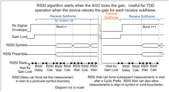
RSSI Restart Modes
RSSI Mode Select |
The RSSI Algorithm will (re)start when |
Useful For |
|---|---|---|
0 |
AGC in Fast Attack Mode Locks the Gain |
TDD |
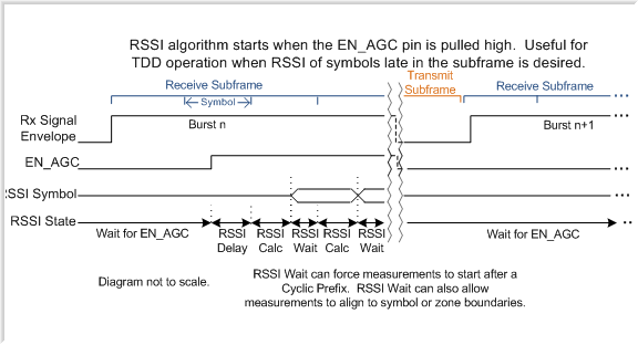
1 |
EN_AGC pin is pulled High |
TDD, measuring a symbol late in the burst |
2 |
AD9361 Enters Rx Mode |
TDD |
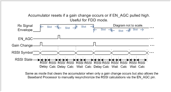
3 |
Gain Change Occurs |
FDD |
4 |
SPI Write to Register |
FDD |
5 |
Gain Change Occurs OR EN_AGC pin pulled High |
FDD |
RSSI Restart Mode 0
RSSI Restart Mode 1
RSSI Restart Mode 2

RSSI Restart Mode 3

RSSI Restart Mode 4

RSSI Restart Mode 5
Example
/* adi,rssi-restart-mode:
 * 0 = AGC_IN_FAST_ATTACK_MODE_LOCKS_THE_GAIN,
 * 1 = EN_AGC_PIN_IS_PULLED_HIGH,
 * 2 = ENTERS_RX_MODE,
 * 3 = GAIN_CHANGE_OCCURS,
 * 4 = SPI_WRITE_TO_REGISTER,
 * 5 = GAIN_CHANGE_OCCURS_OR_EN_AGC_PIN_PULLED_HIGH,
 */
adi,rssi-restart-mode = <3>;
//adi,rssi-unit-is-rx-samples-enable;
adi,rssi-delay = <1>; /* 1us */
adi,rssi-wait = <1>; /* 1us */
adi,rssi-duration = <1000>; /* 1ms */
Control Output Setup
Control Out Setup |
||
|---|---|---|
adi,ctrl-outs-enable-mask |
ctrl_outs_enable_mask |
|
adi,ctrl-outs-index |
ctrl_outs_index |
MASK |
||||||||
INDEX |
[7] |
[6] |
[5] |
[4] |
[3] |
[2] |
[1] |
[0] |
0 |
Cal Done |
TX CP Cal Done |
RX CP Cal Done |
Rx BB Filter Tuning Done |
Tx BB Filter Tuning Done |
Gain Step Cal Busy |
Rx Synth VCO Cal Busy |
Tx Synth VCO Cal Busy |
1 |
Tx RF PLL Lock |
Rx RF PLL Lock |
BB PLL Lock |
0 |
0 |
0 |
0 |
0 |
2 |
BB DC Cal Busy |
RF DC Cal Busy |
CH1 Rx Quad Cal Busy |
CH1 Tx Quad Cal Busy |
CH2 Rx Quad Cal Busy |
CH2 Tx Quad Cal Busy |
Gain Step Cal Busy |
Tx Mon Cal Busy |
3 |
CH1 ADC Low Power |
CH 1 Lg LMT Ovrg |
CH 1 Lg ADC Ovrg |
CH1 Sm ADC Ovrg |
CH 2 Low Power |
CH 2 Lg LMT Ovrg |
CH 2 Lg ADC Ovrg |
CH 2 Sm ADC Ovrg |
4 |
CH 2 Rx Gain[6] |
CH 2 Rx Gain[5] |
CH 2 Rx Gain[4] |
CH 2 Rx Gain[3] |
CH 2 Rx Gain[2] |
CH 2 Lg LMT Ovrg |
CH 2 Lg ADC Ovrg |
CH 2 Gain Lock |
5 |
CH2 Gain Change |
CH1 Gain Change |
CH 2 Low Power |
CH 2 Lg LMT Ovrg |
CH 2 Lg ADC Ovrg |
CH 2 Gain Lock |
CH 2 Energy Lost |
CH2 Stronger Signal |
6 |
CH1Low Power |
CH 1 Lg LMT Ovrg |
CH 1 Lg ADC Ovrg |
CH 1 Rx Gain[6] |
CH 1 Rx Gain[5] |
CH 1 Rx Gain[4] |
CH 1 Rx Gain[3] |
CH 1 Rx Gain[2] |
7 |
CH1 Low Power |
CH 1 Lg LMT Ovrg |
CH 1 Lg ADC Ovrg |
CH1 Sm ADC Ovrg |
CH1 AGC SM[2] |
CH1 AGC SM[1] |
CH1 AGC SM[0] |
CH1 Gain Lock |
8 |
CH 1 Stronger Signal |
CH 1 Gain Lock |
CH 1 Energy Lost |
CH 1 Gain Change |
CH 2 Stronger Signal |
CH 2 Gain Lock |
CH 2 Energy Lost |
CH 2 Gain Change |
9 |
RxOn |
CH 1 RSSI Preamble Ready |
CH 1 RSSI Symbol Ready |
TxOn |
CH 2 RSSI Preamble Ready |
CH 2 RSSI Symbol Ready |
||
10 |
CH 1 Tx Int3 Overflow |
CH 1 Tx HB3 Overflow |
CH 1 Tx HB2 Overflow |
CH 1 Tx QEC Overflow |
CH 1 Tx HB1 Overflow |
CH 1 Tx FIR Overflow |
CH 1 Rx FIR Overflow |
|
11 |
Cal Seq State[3] |
Cal Seq State [2] |
Cal Seq State [1] |
Cal Seq State [0] |
ENSM[3] |
ENSM[2] |
ENSM[1] |
ENSM[0] |
12 |
CH 1 Energy Lost |
CH 1 Reset Peak Detect |
CH 2 Energy Lost |
CH 2 Reset Peak Detect |
Gain Freeze |
CH 1 Digital Sat |
CH 2 Digital Sat |
|
13 |
CH1 Tx Quad Cal Status[1] |
CH1 Tx Quad Cal Status[0] |
CH1 Tx Quad Cal Done |
RF DC Cal Busy |
CH2 Tx Quad Cal Status[1] |
CH2 Tx Quad Cal Status[0] |
CH2 Tx Quad Cal Done |
|
14 |
CH1 Rx Quad Cal Status[1] |
CH1 Rx Quad Cal Status[0] |
CH1 Rx Quad Cal Done |
BB DC Cal Busy |
CH2 Rx Quad Cal Status[1] |
CH2 Rx Quad Cal Status[0] |
CH2 Rx Quad Cal Done |
|
15 |
CH1 AGC State[2] |
CH1 AGC State[1] |
CH1 AGC State[0] |
Reset Peak Detect CH1 |
Reset Peak Detect CH2 |
CH 1 RF DC Cal State[1] |
CH 1 RF DC Cal State[0] |
|
16 |
CH2 AGC State[2] |
CH2 AGC State[1] |
CH2 AGC State[0] |
CH 2 Enable RSSI |
CH 1Enable RSSI |
CH 2 RF DC Cal State[1] |
CH 2 RF DC Cal State[0] |
|
17 |
AuxADC Output[11] |
AuxADC Output[10] |
AuxADC Output[9] |
AuxADC Output[8] |
AuxADC Output[7] |
AuxADC Output[6] |
AuxADC Output[5] |
AuxADC Output[4] |
18 |
CH 1 Filter Power Ready |
CH 1 Gain Lock |
CH 1 Energy Lost |
CH 1 Stronger Signal |
CH 1 ADC Power Ready |
CH 1 AGC State [2] |
CH 1 AGC State [1] |
CH 1 AGC State [0] |
19 |
CH 2 Filter Power Ready |
CH 2 Gain Lock |
CH 2 Energy Lost |
CH 2 Stronger Signal |
CH 2 ADC Power Ready |
CH 2 AGC State [2] |
CH 2 AGC State [1] |
CH 2 AGC State [0] |
20 |
CH 2 Tx Int3 Overflow |
CH 2 Tx HB3 Overflow |
CH 2 Tx HB2 Overflow |
CH 2 Tx QEC Overflow |
CH 2 Tx HB1 Overflow |
CH 2 Tx FIR Overflow |
CH 2 Rx FIR Overflow |
0 |
21 |
CH1 SOI Present |
CH1 Update DCRF |
CH1 Measure DCRF |
CH1 DC Track Count Reached |
0 |
0 |
0 |
0 |
22 |
CH1 Gain Lock |
CH1 Rx Gain[6] |
CH1 Rx Gain[5] |
CH1 Rx Gain[4] |
CH1 Rx Gain[3] |
CH1 Rx Gain[2] |
CH1 Rx Gain[1] |
CH1 Rx Gain[0] |
23 |
CH2 Gain Lock |
CH2 Rx Gain[6] |
CH2 Rx Gain[5] |
CH2 Rx Gain[4] |
CH2 Rx Gain[3] |
CH2 Rx Gain[2] |
CH2 Rx Gain[1] |
CH2 Rx Gain[0] |
24 |
CH2 SOI Present |
CH2 Update DCRF |
CH2 Measure DCRF |
CH2 DC Track Count Reached |
CH2Enable Dec Pwr |
CH2 Enable ADC Pwr |
CH1 Enable Dec Pwr |
CH1 Enable ADC Pwr |
25 |
RX Syn Cp Cal[3] |
RX Syn Cp Cal[2] |
RX Syn Cp Cal[1] |
RX Syn Cp Cal[0] |
TX Syn Cp Cal[3] |
TX Syn Cp Cal[2] |
TX Syn Cp Cal[1] |
TX Syn Cp Cal[0] |
26 |
RX Syn VCO Tuning[8] |
RX Synth VCO ALC[6] |
RX Synth VCO ALC[5] |
RX Synth VCO ALC[4] |
RX Synth VCO ALC[3] |
RX Synth VCO ALC[2] |
RX Synth VCO ALC[1] |
RX Synth VCO ALC[0] |
27 |
TX Syn VCO Tuning[8] |
TX Synth VCO ALC[6] |
TX Synth VCO ALC[5] |
TX Synth VCO ALC[4] |
TX Synth VCO ALC[3] |
TX Synth VCO ALC[2] |
TX Synth VCO ALC[1] |
TX Synth VCO ALC[0] |
28 |
RX Syn VCO Tuning[7] |
RX Syn VCO Tuning[6] |
RX Syn VCO Tuning[5] |
RX Syn VCO Tuning[4] |
RX Syn VCO Tuning[3] |
RX Syn VCO Tuning[2] |
RX Syn VCO Tuning[1] |
RX Syn VCO Tuning[0] |
29 |
TX Syn VCO Tuning[7] |
TX Syn VCO Tuning[6] |
TX Syn VCO Tuning[5] |
TX Syn VCO Tuning[4] |
TX Syn VCO Tuning[3] |
TX Syn VCO Tuning[2] |
TX Syn VCO Tuning[1] |
TX Syn VCO Tuning[0] |
30 |
CH1Low Thresh Exceeded |
CH1High Thresh Exceeded |
CH1Gain Upd Count Exp |
CH1AGC State [1] |
CH1AGC State [0] |
CH 1 Gain Change |
Temp Sense Valid |
AuxADC Valid |
31 |
CH2Low Thresh Exceeded |
CH2High Thresh Exceeded |
CH2Gain Upd Count Exp |
CH2AGC SM[1] |
CH2AGC SM[0] |
CH 2 Gain Change |
Clock Output Setup
CLKOUT |
CLKOUT Frequency |
|---|---|
0 |
Disabled |
1 |
XTALN (or DCXO) (buffered) |
2 |
ADC_CLK / 2 |
3 |
ADC_CLK / 3 |
4 |
ADC_CLK / 4 |
5 |
ADC_CLK / 8 |
6 |
ADC_CLK / 16 |
7 |
ADC_CLK / 32 |
8 |
ADC_CLK / 64 |