AD5592R
AD5592R IIO DAC/ADC.
Supported Devices
Reference Circuits
Evaluation Boards
Description
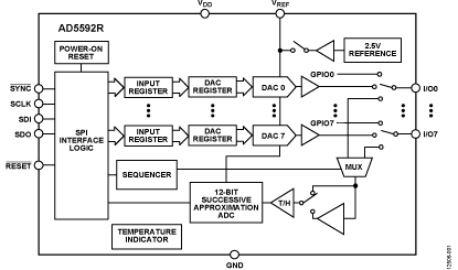
The AD5592R/AD5592R-1 have eight I/Ox pins (I/O0 to I/O7) that can be independently configured as digital-to-analog converter (DAC) outputs, analog-to-digital converter (ADC) inputs, digital outputs, or digital inputs.
When an I/Ox pin is configured as an analog output, it is driven by a 12-bit DAC. The output range of the DAC is 0 V to VREF or 0 V to 2 × VREF.
When an I/Ox pin is configured as an analog input, it is connected to a 12-bit ADC via an analog multiplexer. The input range of the ADC is 0 V to VREF or 0 V to 2 × VREF. The ADC has a total throughput rate of 400 kSPS.
The I/Ox pins can also be configured as digital, general-purpose input or output (GPIO) pins. The state of the GPIO pins can be set or read back by accessing the GPIO write data register or the GPIO read configuration register, respectively, via a serial peripheral interface (SPI) write or read operation.
The AD5592R/AD5592R-1 have an integrated 2.5 V, 25 ppm/°C reference, which is turned off by default, and an integrated temperature indicator, which gives an indication of the die temperature. The temperature value is read back as part of an ADC read sequence.
Source Code
Status
Files
Function |
File |
|
|---|---|---|
driver |
||
include |
||
driver |
||
include |
||
Documentation |
Hardware configuration

Adding Linux driver support
Enabling the driver
Configure kernel with make menuconfig (alternatively use make xconfig or
make qconfig)
Note
The AD5592R Driver depends on CONFIG_SPI_MASTER
Linux Kernel Configuration
    Device Drivers  --->
        ...
        <*>     Industrial I/O support --->
            --- Industrial I/O support
            ...
            Digital to analog converters  --->
                ...
                <*>   Analog Devices AD5592R ADC/DAC driver
                ...
            ...
        ...
Adding a device tree entry
Required properties
compatible: Must be one of:
adi,ad5592r
reg: SPI chip select number for the device
spi-max-frequency: Max SPI frequency to use (< 30000000)
spi-cpol: The AD5592R requires inverse clock polarity (CPOL) mode
#address-cells: Should be 1.
#size-cells: Should be 0.
channel nodes:
Each child node represents one channel and has the following
Required properties:
reg: Pin on which this channel is connected to.
adi,mode: Mode or function of this channel. Macros specifying the valid values can be found in <dt-bindings/iio/adi,ad5592r.h>. The following values are currently supported:
CH_MODE_UNUSED (the pin is unused)
CH_MODE_ADC (the pin is ADC input)
CH_MODE_DAC (the pin is DAC output)
CH_MODE_DAC_AND_ADC (the pin is DAC output but can be monitored by an ADC, since there is no disadvantage this this should be considered as the preferred DAC mode)
CH_MODE_GPIO (the pin is registered with GPIOLIB)
Optional properties:
adi,off-state: State of this channel when unused or the device is removed. Macros specifying the valid values can be found in <dt-bindings/iio/adi,ad5592r.h>.
CH_OFFSTATE_PULLDOWN (the pin is pulled down)
CH_OFFSTATE_OUT_LOW (the pin is output low)
CH_OFFSTATE_OUT_HIGH (the pin is output high)
CH_OFFSTATE_OUT_TRISTATE (the pin is tristated output)
Optional properties
vref-supply: Phandle to the external reference voltage supply. This should only be set if there is an external reference voltage connected to the VREF pin. If the property is not set the internal 2.5V reference is used.
reset-gpios : GPIO spec for the RESET pin. If specified, it will be asserted during driver probe.
gpio-controller: Marks the device node as a GPIO controller.
#gpio-cells: Should be 2. The first cell is the GPIO number and the second cell specifies GPIO flags, as defined in <dt-bindings/gpio/gpio.h>.
Device tree example
The following example instanciates the ad5592r driver for a AD5592R device connected on the SPI bus to the chip-select line 0. It sets the I/O0 port as a DAC, the I/O1 port as ADC. I/O2 and I/O3 are configured for primary function DAC the additional ADC can measure the voltage being provided by the DAC. This feature can monitor the output voltage to detect short circuits or overload conditions. I/O4 is connected to the ground with a pull-down resistor. The other I/Os are registered with the Linux GPIO subsystem.
#include <dt-bindings/iio/adi,ad5592r.h>

vref: regulator-vref {
    compatible = "regulator-fixed";
    regulator-name = "vref-ad559x";
    regulator-min-microvolt = <3300000>;
    regulator-max-microvolt = <3300000>;
    regulator-always-on;
};

ad5592r@0 {
    #size-cells = <0>;
    #address-cells = <1>;
    #gpio-cells = <2>;
    compatible = "adi,ad5592r";
    reg = <0>;

    spi-max-frequency = <1000000>;
    spi-cpol;

    vref-supply = <&vref>; /* optional */
    reset-gpios = <&gpio0 86 0>;  /* optional */
    gpio-controller;

    channel@0 {
        reg = <0>;
        adi,mode = <CH_MODE_DAC>;
    };
    channel@1 {
        reg = <1>;
        adi,mode = <CH_MODE_ADC>;
    };
    channel@2 {
        reg = <2>;
        adi,mode = <CH_MODE_DAC_AND_ADC>;
    };
    channel@3 {
        reg = <3>;
        adi,mode = <CH_MODE_DAC_AND_ADC>;
        adi,off-state = <CH_OFFSTATE_PULLDOWN>;
    };
    channel@4 {
        reg = <4>;
        adi,mode = <CH_MODE_UNUSED>;
        adi,off-state = <CH_OFFSTATE_PULLDOWN>;
    };
    channel@5 {
        reg = <5>;
        adi,mode = <CH_MODE_GPIO>;
        adi,off-state = <CH_OFFSTATE_PULLDOWN>;
    };
    channel@6 {
        reg = <6>;
        adi,mode = <CH_MODE_GPIO>;
        adi,off-state = <CH_OFFSTATE_PULLDOWN>;
    };
    channel@7 {
        reg = <7>;
        adi,mode = <CH_MODE_GPIO>;
        adi,off-state = <CH_OFFSTATE_PULLDOWN>;
    };
};
Driver testing
If the driver correctly detected the device, the iio_info program should
inform us about the available channels:
root@linaro-ubuntu-desktop:~# iio_info
IIO context created: local
IIO context has 3 devices:
        iio:device2: ad5593r
                7 channels found:
                        voltage0:  (output)
                        3 channel-specific attributes found:
                                attr 0: raw value: 0
                                attr 1: scale_available value: 0.732421875 1.464843750
                                attr 2: scale value: 0.732421875
                        voltage2:  (output)
                        3 channel-specific attributes found:
                                attr 0: raw value: 0
                                attr 1: scale_available value: 0.732421875 1.464843750
                                attr 2: scale value: 0.732421875
                        voltage3:  (output)
                        3 channel-specific attributes found:
                                attr 0: raw value: 0
                                attr 1: scale_available value: 0.732421875 1.464843750
                                attr 2: scale value: 0.732421875
                        voltage1:  (input)
                        3 channel-specific attributes found:
                                attr 0: raw value: 0
                                attr 1: scale value: 0.732421875
                                attr 2: scale_available value: 0.732421875 1.464843750
                        voltage2:  (input)
                        3 channel-specific attributes found:
                                attr 0: raw value: 1
                                attr 1: scale value: 0.732421875
                                attr 2: scale_available value: 0.732421875 1.464843750
                        voltage3:  (input)
                        3 channel-specific attributes found:
                                attr 0: raw value: 0
                                attr 1: scale value: 0.732421875
                                attr 2: scale_available value: 0.732421875 1.464843750
                        temp:  (input)
                        3 channel-specific attributes found:
                                attr 0: offset value: -628
                                attr 1: raw value: 680
                                attr 2: scale value: 452.147700000
IIO sysfs interface
root@linaro-ubuntu-desktop:/sys/bus/iio/devices/iio:device2# ls -al
total 0
drwxr-xr-x 3 root root    0 Jan  1  1970 .
drwxr-xr-x 5 root root    0 Jan  1  1970 ..
-rw-rw-rw- 1 root root 4096 Jan  1  1970 dev
-rw-rw-rw- 1 root root 4096 Jan  1  1970 in_temp_offset
-rw-rw-rw- 1 root root 4096 Jan  1  1970 in_temp_raw
-rw-rw-rw- 1 root root 4096 Jan  1  1970 in_temp_scale
-rw-rw-rw- 1 root root 4096 Jan  1  1970 in_voltage1_raw
-rw-rw-rw- 1 root root 4096 Jan  1  1970 in_voltage2_raw
-rw-rw-rw- 1 root root 4096 Jan  1  1970 in_voltage3_raw
-rw-rw-rw- 1 root root 4096 Jan  1  1970 in_voltage_scale
-rw-rw-rw- 1 root root 4096 Jan  1  1970 in_voltage_scale_available
-rw-rw-rw- 1 root root 4096 Jan  1  1970 name
lrwxrwxrwx 1 root root    0 Jan  1  1970 of_node -> ../../../../../../../firmware/devicetree/base/amba/i2c@e0004000/ad5593r@10
-rw-rw-rw- 1 root root 4096 Jan  1  1970 out_voltage0_raw
-rw-rw-rw- 1 root root 4096 Jan  1  1970 out_voltage2_raw
-rw-rw-rw- 1 root root 4096 Jan  1  1970 out_voltage3_raw
-rw-rw-rw- 1 root root 4096 Jan  1  1970 out_voltage_scale
-rw-rw-rw- 1 root root 4096 Jan  1  1970 out_voltage_scale_available
drwxrwxrwx 2 root root    0 Jan  1  1970 power
lrwxrwxrwx 1 root root    0 Jan  1  1970 subsystem -> ../../../../../../../bus/iio
-rw-rw-rw- 1 root root 4096 Jan  1  1970 uevent
root@linaro-ubuntu-desktop:/sys/bus/iio/devices/iio:device2#
root@linaro-ubuntu-desktop:/sys/bus/iio/devices/iio:device2# grep "" *
dev:252:2
in_temp_offset:-753
in_temp_raw:810
in_temp_scale:376.789750000
in_voltage1_raw:0
in_voltage2_raw:0
in_voltage3_raw:0
in_voltage_scale:0.610351562
in_voltage_scale_available:0.610351562 1.220703124
name:ad5592r
out_voltage0_raw:0
out_voltage2_raw:0
out_voltage3_raw:0
out_voltage_scale:0.610351562
out_voltage_scale_available:0.610351562 1.220703124
uevent:MINOR=2
uevent:DEVNAME=iio:device2
uevent:DEVTYPE=iio_device
uevent:OF_NAME=ad5593r
uevent:OF_FULLNAME=/amba/i2c@e0004000/ad5593r@10
uevent:OF_COMPATIBLE_0=adi,ad5593r
uevent:OF_COMPATIBLE_N=1
Show device name
root@linaro-ubuntu-desktop:/sys/bus/iio/devices/iio:device2# cat name
ad5593r
Scales
The output range of the DAC is 0 V to VREF or 0 V to 2 × VREF. out_voltage_scale is used to select the high or low range. Without external reference the driver selects the internal 2500mV VREF reference. So the scale computes as 2500mV/2^12 = 0.610351562 or 5000mV/2^12 = 1.220703124.
The input range of the ADC is 0 V to VREF or 0 V to 2 × VREF. in_voltage_scale is used to select the high or low range. Without external reference the driver selects the internal 2500mV VREF reference. So the scale computes as 2500mV/2^12 = 0.610351562 or 5000mV/2^12 = 1.220703124.
Show current scale
Description: scale to be applied to out_voltageY_raw/in_voltageY_raw in order to obtain the measured voltage in millivolts.
root@linaro-ubuntu-desktop:/sys/bus/iio/devices/iio:device2# cat out_voltage_scale
0.610351562
Show available scales
Description: scale to be applied to out_voltageY_raw/in_voltageY_raw in order to obtain the measured voltage in millivolts.
root@linaro-ubuntu-desktop:/sys/bus/iio/devices/iio:device2# cat in_voltage_scale_available
0.610351562 1.220703124
Change scales
Description: scale to be applied to out_voltageY_raw/in_voltageY_raw in order to obtain the measured voltage in millivolts.
root@linaro-ubuntu-desktop:/sys/bus/iio/devices/iio:device2# echo 1.220703124 > in_voltage_scale
root@linaro-ubuntu-desktop:/sys/bus/iio/devices/iio:device2# cat in_voltage_scale
1.220703124
Get channel Y input voltage
Description: Raw unscaled voltage measurement on channel Y
This specifies any shell prompt running on the target
root@linaro-ubuntu-desktop:/sys/bus/iio/devices/iio:device2# cat in_voltage3_raw
1491
U = in_voltage3_raw * in_voltage_scale = 1491 * 0.610351562 = 910 mV
Set channel Y output voltage
Description: Raw (unscaled, no bias etc.) output voltage for channel Y.
root@linaro-ubuntu-desktop:/sys/bus/iio/devices/iio:device2# echo 1638 > out_voltage0_raw
U = out_voltage0_raw * out_voltage_scale = 1638 * 0.610351562 = 999.76 mV
Example obtaining the temperature in °C
T = ( in_temp_raw + in_temp_offset ) * in_temp_scale
T = ( 810 - 753 ) * 376.78975 = 21477 mdeg C = 21.5 °C
For more information see also here: IIO Kernel Documentation
GPIO Testing
The GPIO sysfs interface allows users to manipulate any GPIO from userspace. Userspace utilizes a sysfs control interface to dynamically request and release individual GPIOs. Once a GPIO has been requested, writing to the newly created path allows you to control the direction and the data while reading from it returns the GPIO data (which usually corresponds to a 0 or 1 which represents the signal level).
For more information see also here: GPIO Kernel Documentation
root@linaro-ubuntu-desktop:~# cd /sys/class/gpio/
root@linaro-ubuntu-desktop:/sys/class/gpio# ls
export  gpiochip890  gpiochip898  gpiochip906  unexport

root@linaro-ubuntu-desktop:/sys/class/gpio# cd gpiochip890

root@linaro-ubuntu-desktop:/sys/class/gpio/gpiochip890# ls -al
total 0
drwxr-xr-x 3 root root    0 Jan  1  1970 .
drwxr-xr-x 3 root root    0 Jan  1  1970 ..
-r--r--r-- 1 root root 4096 Feb 23 08:06 base
lrwxrwxrwx 1 root root    0 Feb 23 08:06 device -> ../../../0-0010
-r--r--r-- 1 root root 4096 Feb 23 08:06 label
-r--r--r-- 1 root root 4096 Feb 23 08:06 ngpio
drwxr-xr-x 2 root root    0 Feb 23 08:06 power
lrwxrwxrwx 1 root root    0 Jan  1  1970 subsystem -> ../../../../../../../../class/gpio
-rw-r--r-- 1 root root 4096 Jan  1  1970 uevent

root@linaro-ubuntu-desktop:/sys/class/gpio/gpiochip890# grep "" *
base:890
label:0-0010
ngpio:8

root@linaro-ubuntu-desktop:/sys/class/gpio/gpiochip890# cd ..
root@linaro-ubuntu-desktop:/sys/class/gpio# echo 897 > export
root@linaro-ubuntu-desktop:/sys/class/gpio# cd gpio897/
root@linaro-ubuntu-desktop:/sys/class/gpio/gpio897# ls -al
total 0
drwxr-xr-x 3 root root    0 Feb 23 08:06 .
drwxr-xr-x 4 root root    0 Feb 23 08:06 ..
-rw-r--r-- 1 root root 4096 Feb 23 08:06 active_low
lrwxrwxrwx 1 root root    0 Feb 23 08:06 device -> ../../../0-0010
-rw-r--r-- 1 root root 4096 Feb 23 08:06 direction
drwxr-xr-x 2 root root    0 Feb 23 08:06 power
lrwxrwxrwx 1 root root    0 Feb 23 08:06 subsystem -> ../../../../../../../../class/gpio
-rw-r--r-- 1 root root 4096 Feb 23 08:06 uevent
-rw-r--r-- 1 root root 4096 Feb 23 08:06 value

root@linaro-ubuntu-desktop:/sys/class/gpio/gpio897# cat direction
in

root@linaro-ubuntu-desktop:/sys/class/gpio/gpio897# cat value
0

root@linaro-ubuntu-desktop:/sys/class/gpio/gpio897# echo low > direction

root@linaro-ubuntu-desktop:/sys/class/gpio/gpio897# cat direction
out

root@linaro-ubuntu-desktop:/sys/class/gpio/gpio897# cat value
0

root@linaro-ubuntu-desktop:/sys/class/gpio/gpio897# echo high > direction

root@linaro-ubuntu-desktop:/sys/class/gpio/gpio897# cat value
1