JESD204 FSM
JESD204 FSM Interface Linux Kernel Framework.
The JESD204 Linux Kernel Framework is a Finite State Machine (FSM) that is meant to synchronize other Linux device drivers to be able to properly bring-up & manage a single or multiple JESD204 links.
The JESD204 link bring-up and management is complicated, and it requires that many actors (device drivers), be in sync with each other, in various link bring-up states/stages. Typical components of an JESD204 link are the physical layer (PHY), link layer (LL), transport layer (TPL) and the high speed converter device and clocking layer with all it’s constrains and inter-dependencies. This has to happen not just at boot-time, but also during run-time, in case a link is going to be reconfigured or breaks and has to recover.
To achieve this, the JESD204 Linux Kernel Framework hooks into all the drivers that participate in the link management (bring-up/bring-down) and each driver provides a set of callbacks for each state that it supports.
The relationship between the devices is defined in the device-tree. The relationship is called a connection so as not to re-use the term link, which can cause confusion with the term link from the JESD204 standard. The whole group of devices, is actually a graph (or topology), with a single top-level device.
Device Topology
JESD204 devices form a directed graph (topology) where connections represent
data flow between devices. The topology is defined in Device Tree using
jesd204-inputs properties that specify parent-child relationships.
================================================================================
                         JESD204 Topology Graph
================================================================================

                          +--------------------------+
                          | ad9081@0                 |
                          | [TOP]                    |
                          +--------------------------+
                                        |
                                        v

           +--------------------------+  +--------------------------+
           | axi-ad9081-rx-hpc@8      |  | axi-ad9081-tx-hpc@8      |
           |                          |  |                          |
           +--------------------------+  +--------------------------+
                         |                             |
                         v                             v

           +--------------------------+  +--------------------------+
           | axi-jesd204-rx@8         |  | axi-jesd204-tx@8         |
           |                          |  |                          |
           +--------------------------+  +--------------------------+
                         |                             |
                         v                             v

           +--------------------------+  +--------------------------+
           | axi-adxcvr-rx@8          |  | axi-adxcvr-tx@8          |
           |                          |  |                          |
           +--------------------------+  +--------------------------+
                         |                             |
                         v                             v

                          +--------------------------+
                          | hmc7044@0                |
                          | [CLK]                    |
                          +--------------------------+

Legend: [TOP] = Top device (ADC/DAC)  [CLK] = Clock/SYSREF source

--------------------------------------------------------------------------------
Link 2 - RX (JESD204B)  State: opt_post_running_stage
--------------------------------------------------------------------------------
  JESD Parameters:  L=8  M=4  N=16  N'=16  F=1  K=32  S=1
  Encoder: 8B/10B    Subclass: 1  Scrambling: Yes  HD: No
  Sample Rate:  1.500000000000 GHz
  Lane Rate:    15.000000000000 GHz
  LMFC Rate:   46.875000000 MHz
  Device Clock: 375.000000000 MHz

--------------------------------------------------------------------------------
Link 0 - TX (JESD204B)  State: opt_post_running_stage
--------------------------------------------------------------------------------
  JESD Parameters:  L=8  M=4  N=16  N'=16  F=1  K=32  S=1
  Encoder: 8B/10B    Subclass: 1  Scrambling: Yes  HD: No
  Sample Rate:  1.500000000000 GHz
  Lane Rate:    15.000000000000 GHz
  LMFC Rate:   46.875000000 MHz
  Device Clock: 375.000000000 MHz
Each topology has:
Top-level device: Initiates state transitions and defines link IDs
Input connections: Declared via
jesd204-inputspropertyLink IDs: Specify which JESD204 link(s) a device participates in
Device Tree Properties
jesd204-device
Boolean property marking a node as a JESD204 device.
jesd204-top-device
Marks device as the top-level device. Value is the topology ID.
jesd204-link-ids
Array of link IDs this top device manages.
jesd204-inputs
Array of phandles with arguments: <&parent_device topo_id link_id>
jesd204-sysref-provider
Marks this device as the primary SYSREF provider for the topology.
jesd204-secondary-sysref-provider
Marks this device as a secondary SYSREF provider (for link recovery).
jesd204-stop-states
Array of state indices where the FSM should pause (for multi-topology sync).
jesd204-ignore-errors
Boolean to continue despite errors (useful for debugging).
To illustrate, here’s an example device-tree and below it how the graph representation looks like for an ADRV9009 FMC card on a ZC706.
// SPDX-License-Identifier: GPL-2.0
/*
 * Analog Devices ADRV9009 (via jesd204-fsm)
 * https://wiki.analog.com/resources/eval/user-guides/adrv9009
 * https://wiki.analog.com/resources/tools-software/linux-drivers/iio-transceiver/adrv9009
 * https://wiki.analog.com/resources/tools-software/linux-software/adrv9009_advanced_plugin
 *
 * hdl_project: <adrv9009/zc706>
 * board_revision: <>
 *
 * Copyright (C) 2020 Analog Devices Inc.
 */

#include "zynq-zc706-adv7511-adrv9009.dts"

#include <dt-bindings/iio/adc/adi,adrv9009.h>

&trx0_adrv9009 {
    jesd204-device;
    #jesd204-cells = <2>;
    jesd204-top-device = <0>; /* This is the TOP device */
    jesd204-link-ids = <DEFRAMER_LINK_TX FRAMER_LINK_RX FRAMER_LINK_ORX>;

    jesd204-inputs =
        <&axi_adrv9009_rx_jesd 0 FRAMER_LINK_RX>,
        <&axi_adrv9009_rx_os_jesd 0 FRAMER_LINK_ORX>,
        <&axi_adrv9009_tx_jesd 0 DEFRAMER_LINK_TX>;

    /delete-property/ interrupts;
};

&axi_adrv9009_rx_jesd {
    jesd204-device;
    #jesd204-cells = <2>;
    jesd204-inputs = <&axi_adrv9009_adxcvr_rx 0 FRAMER_LINK_RX>;
};

&axi_adrv9009_rx_os_jesd {
    jesd204-device;
    #jesd204-cells = <2>;
    jesd204-inputs = <&axi_adrv9009_adxcvr_rx_os 0 FRAMER_LINK_ORX>;
};

&axi_adrv9009_tx_jesd {
    jesd204-device;
    #jesd204-cells = <2>;
    jesd204-inputs = <&axi_adrv9009_adxcvr_tx 0 DEFRAMER_LINK_TX>;
};

&axi_adrv9009_adxcvr_rx {
        jesd204-device;
    #jesd204-cells = <2>;
    jesd204-inputs =  <&clk0_ad9528 0 FRAMER_LINK_RX>;
    clocks = <&clk0_ad9528 1>; /* div40 is controlled by axi_adrv9009_rx_jesd */
    clock-names = "conv";
};

&axi_adrv9009_adxcvr_rx_os {
        jesd204-device;
    #jesd204-cells = <2>;
    jesd204-inputs =  <&clk0_ad9528 0 FRAMER_LINK_ORX>;
    clocks = <&clk0_ad9528 1>; /* div40 is controlled by axi_adrv9009_rx_os_jesd */
    clock-names = "conv";
};

&axi_adrv9009_adxcvr_tx {
        jesd204-device;
    #jesd204-cells = <2>;
    jesd204-inputs =  <&clk0_ad9528 0 DEFRAMER_LINK_TX>;
    clocks = <&clk0_ad9528 1>; /* div40 is controlled by axi_adrv9009_tx_jesd */
    clock-names = "conv";
};

&clk0_ad9528 {
    jesd204-device;
    #jesd204-cells = <2>;
    jesd204-sysref-provider;

    adi,sysref-pattern-mode = <SYSREF_PATTERN_NSHOT>;
    /delete-property/ adi,sysref-request-enable;
};
The structure above translates to the image below.
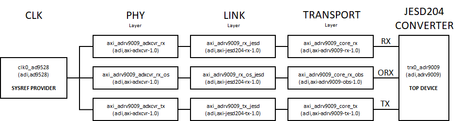
Design Principles
The picture in the diagram makes thinks look really simple, but in reality they aren’t. If any of the devices in that topology/graph has a change of state, or an error occurs, multiple devices must be re-synchronized.
Also, the device-tree described above, is an actual working device-tree. Some variations may be found in the ADI Linux kernel repository (i.e. some more nodes in-between the nodes described above).
There may be other frameworks in Linux that describe this topology, but the challenge with JESD204 is that (at this current point in time), there is no clear idea of the minimum amount of states needed to synchronize or re-synchronize in order to recover a JESD204 link if it goes down.
The end-result is an FSM that tries to make all the devices go through the same states at once.
Some design principles, defined so far for this framework:
A group of devices shall be named a topology (or informally graph or tree); while the picture above looks simple, more complicated topologies should be support with this framework
Each topology shall have a single top-level device; for a multi-chip topology, one will be picked to be the top-level one. For IIO devices, it is assumed that this device will also register the IIO buffer.
Each device driver must register with the JESD204 framework to be able to take part in a topology
A device may only be part of a topology, if it is defined in the device-tree (or other configuration mechanism) via a ‘jesd204-device’ node/definition.
A top-level device may be defined via ‘jesd204-top-device = <ID>’ ; ID is a number defining the topology ID, to be able to specify more topologies
The top-level device defines the JESD204 link IDs in the device-tree (via ‘jesd204-link-ids’ array property); the order in this array, is the order in which the JESD204 links are initialized;
Each device declares its connections using the jesd204-inputs list array property. The jesd-inputs are declared using following syntax: jesd204-inputs = <phandleX TOPOLOGY_ID LINK_ID_X>, <phandleY TOPOLOGY_ID LINK_ID_Y>, …
All devices in a topology must go through the same states together when bringing up a link and in the same order reverse in reverse when bringing down or rolling back; example: all 8 devices must go from S0 to S9 together, and S9 to S0 together
When going through each state, each device-driver will provide it’s own set of callbacks for what to do in each state; if a callback it is not provided, it is assumed that the device-driver doesn’t care about that specific state, and the transition will continue
When an error occurs in any of the states, the states should automatically be rolled back from the state that has errored back to the initial/idle state; so, if going from S0 to S9 and S3 faults, the transition will be S0, S1, S2, S3, S2, S1, S0 (in perfect symmetry)
Rolling back doesn’t stop even when any of the states errors out; it is of higher priority to reach back to IDLE state, than to stop when rolling back
Each callback (in the driver) must return either JESD204_STATE_CHANGE_DONE (value 1) or JESD204_STATE_CHANGE_DEFER (value 0), or an error if it occurs (any negative value). The decision was made for JESD204_STATE_CHANGE_DONE to be 1, so that when a new driver implements a callback for a framework,
return 0doesn’t meanDONE(i.e. accidental/unwanted state transitions);The JESD204_STATE_CHANGE_DEFER is important if a state should stop (but not rollback) and wait for an external call (a thread/retry mechanism) to restart the FSM and continue from the current state; so when transitioning from state S0 to S9, and S4 calls for a DEFER, the FSM will stop at S4, and an external entity (retry loop, workq,interrupt ,etc) would call the FSM to continue the transition up to S9; the DEFER mechanism/logic allows us to pause a transition of states if any device (in the topology) calls for it (because it isn’t ready yet)
For any particular state, the callbacks of the top-level device must be called last; for the other devices it shouldn’t matter; the top-level is typically the ADC/DAC/XCVR, so it is important that this is called last to enable/disable the final bits of a link
There can be only a single device that can act as a SYSREF provider in a topology; defining more than one will fail the initialization of the topology
TL;DR - show me the code
The current source code of the JESD204 Linux framework resides in drivers/jesd204/
It is comprised of the current source files:
jesd204-core.c - the core file of the framework - it reads the device-tree, constructs the topology
jesd204-fsm.c - the entire FSM logic
jesd204-sysfs.c - the Linux sysfs code to export files for debug/control/etc under /sys/bus/jesd204/devices/jesd204:X
jesd204-priv.h - internal framework structures/functions to be shared inside the framework
include/linux/jesd204/jesd204.h - API definitions to be used by drivers registering with the framework
How does it work?
A typical driver needs to provide some data to the framework. Example (for ADRV9009):
static const struct jesd204_dev_data jesd204_adrv9009_init = {
    .state_ops = {
        [JESD204_OP_DEVICE_INIT] = {
            .per_device = adrv9009_jesd204_uninit,
        },
        [JESD204_OP_LINK_INIT] = {
            .per_link = adrv9009_jesd204_link_init,
        },
        [JESD204_OP_CLOCKS_ENABLE] = {
            .per_link = adrv9009_jesd204_clks_enable,
        },
        [JESD204_OP_LINK_SETUP] = {
            .per_device = adrv9009_jesd204_link_setup,
            .mode = JESD204_STATE_OP_MODE_PER_DEVICE,
            .post_state_sysref = true,
        },
        [JESD204_OP_LINK_ENABLE] = {
            .per_link = adrv9009_jesd204_link_enable,
            .post_state_sysref = true,
        },
        [JESD204_OP_LINK_RUNNING] = {
            .per_link = adrv9009_jesd204_link_running,
        },
        [JESD204_OP_OPT_SETUP_STAGE1] = {
            .per_device = adrv9009_jesd204_setup_stage1,
            .mode = JESD204_STATE_OP_MODE_PER_DEVICE,
            .post_state_sysref = true,
        },
        [JESD204_OP_OPT_SETUP_STAGE2] = {
            .per_device = adrv9009_jesd204_setup_stage2,
            .mode = JESD204_STATE_OP_MODE_PER_DEVICE,
            .post_state_sysref = true,
        },
        [JESD204_OP_OPT_SETUP_STAGE3] = {
            .per_device = adrv9009_jesd204_setup_stage3,
            .mode = JESD204_STATE_OP_MODE_PER_DEVICE,
            .post_state_sysref = true,
        },
        [JESD204_OP_OPT_SETUP_STAGE4] = {
            .per_device = adrv9009_jesd204_setup_stage4,
            .mode = JESD204_STATE_OP_MODE_PER_DEVICE,
        },
        [JESD204_OP_OPT_SETUP_STAGE5] = {
            .per_device = adrv9009_jesd204_setup_stage5,
            .mode = JESD204_STATE_OP_MODE_PER_DEVICE,
        },
        [JESD204_OP_OPT_POST_RUNNING_STAGE] = {
            .per_device = adrv9009_jesd204_post_running_stage,
            .mode = JESD204_STATE_OP_MODE_PER_DEVICE,
        },
    },

    .max_num_links = 3,
    .sizeof_priv = sizeof(struct adrv9009_jesd204_priv),
};
The driver needs to call devm_jesd204_dev_register(). All this does, is to bind the driver from the probe the device-tree binding/definition for this device’s place in a JESD204 topology. If the devm_jesd204_dev_register() function returns NULL, this driver is not part of any JESD204 topology/operation. For example, some clock-chip drivers can operate as clock-drivers, or as JESD204 providers.
Example:
jdev = devm_jesd204_dev_register(&spi->dev, jesd204_init);
if (IS_ERR(jdev))
    return PTR_ERR(jdev);
All drivers must finally call (in probe) the jesd204_fsm_start() on their object from the framework. This is true for all devices, even the ones that are not top-level devices.
Example:
ret = jesd204_fsm_start(jdev, JESD204_LINKS_ALL);
If jdev is NULL, that is fine. Typically, a driver may call this FSM for all JESD204 links that are defined in the device-tree. With the sysfs, the jesd204_fsm_start() may be called for a single JESD204 link.
There’s an equivalent jesd204_fsm_stop() that will stop the FSM.
The proper functioning of the FSM relies on the driver correctly using the framework and that that connections between devices be properly defined in the device-tree.
The initialization data
The initialization data has type:
/**
 * struct jesd204_dev_data - JESD204 device initialization data
 * @sysref_cb       SYSREF callback, if this device/driver supports it
 * @sizeof_priv     amount of data to allocate for private information
 * @links       JESD204 initial link configuration
 * @max_num_links   maximum number of JESD204 links this device can support
 * @num_retries     number of retries in case of error (only for top-level device)
 * @state_ops       ops for each state transition of type @struct jesd204_state_op
 */
struct jesd204_dev_data {
    jesd204_sysref_cb           sysref_cb;
    size_t                  sizeof_priv;
    const struct jesd204_link       *links;
    unsigned int                max_num_links;
    unsigned int                num_retries;
    struct jesd204_state_op         state_ops[__JESD204_MAX_OPS];
};
A SYSREF provider hooks itself with the sysref_cb hook, but there also must be a device-tree property to mark that this is the SYSREF provider used in the topology.
Optionally a driver may reserve some memory for private state data via sizeof_priv and can be obtained via a jesd204_dev_priv(jdev)
The links field is used to define JESD204 links in a static manner in the driver; these may go away if there aren’t any clear use-cases for them; but it could be that some devices allow only a fixed configuration, so these could be useful in those cases
max_num_links - maximum number of JESD204 links that this device supports; the actual number will be configured from the device-tree, but it shouldn’t exceed this number
num_retries - number of retries in case of error during an FSM start/link-bring-up
state_ops - more below
Each driver hooks it’s callback by adding the proper entry in the state_ops array. The type of a state_op is defined as (may be subject to change):
/**
 * struct jesd204_state_op - JESD204 device per-state op
 * @mode        mode for this state op, depending on this @per_device or @per_link is called
 * @per_device      op called for each JESD204 **device** during a transition
 * @per_link        op called for each JESD204 **link** individually during a transition
 * @post_state_sysref   true if a SYSREF should be issued after the state change
 */
struct jesd204_state_op {
    enum jesd204_state_op_mode  mode;
    jesd204_dev_cb          per_device;
    jesd204_link_cb         per_link;
    bool                post_state_sysref;
};
During a state-transition a state callback will be called:
once for each JESD204 link if the mode is default JESD204_STATE_OP_MODE_PER_LINK; in this case the per_link callback is called
once for each device (regardless of the number of JESD204 links per device) if mode is JESD204_STATE_OP_MODE_PER_DEVICE; in this case the per_device callback is called;
It’s unsure (yet) whether it makes sense to call both per_link and per_device callbacks for a state. It could be an option at a later point in time.
Optionally, each state may request a SYSREF call, by setting post_state_sysref to true.
JESD204-FSM link states in a nutshell
Important JESD204-FSM link states in a nutshell.
LINK_INIT The JESD204-FSM calls this callback for each JESD204 link defined
in the device-tree. The TOP device fills in the (struct jesd204_link)
parameter for each link. These parameters include all the JESD204 link
parameters, the sample rate and SYSREF mode settings, such as continuous or
pulsed SYSREF operation.
LINK_SUPPORTED During this state the FSM core, calls for each link of a topology into each device in order to query if this configuration is supported. Whether a configuration is supported or not depends on a number of constrains and synthesis parameters. In case all devices support the configuration, the FSM moves on to the next state. The clock chip drivers use this state to compute the LMFC/LEMC of all links and find it’s GCD, so that a common SYSREF frequency can be computed which satisfies all links requirements.
LINK_PRE_SETUP Typically, this state is used by the CLK chip drivers to configure the output channels dedicated as SYSREF, applies the previously computed SYSREF frequency and configures the mode.Optional CLK_SYNC_STAGEs These states can be used by clock chip drivers to implement a Clock Tree Synchronization mechanism. This is typically device specific or might not be supported by the clock chip in question. Right now, there are 3 states reserved for this. Based on the HMC7044 example this is what happens in each state.
CLK_SYNC_STAGE1 The SYNC provider and consumers are configured to generate or receive a synchronization request.
CLK_SYNC_STAGE2 The synchronization request is issued at the TOP most device in the clock tree. For the HMC7044, this is the SYSREF PROVIDER.
CLK_SYNC_STAGE3 In this last CLK SYNC state, the SYNC status of each CLK device is validated.
LINK_SETUP In this state all actors (link devices) are setup and configured, based on the mode and configuration previously validated. A lot of devices typically found on multi-chip setups, require additional synchronization steps such as MCS (Mult-chip Sync), Phase/NCO Sync, or calibrations which take a lot of time and would benefit from being done in parallel to save some time. For those cases OPT_SETUP_STAGE1 to OPT_SETUP_STAGE5 can be used to implement these High-Speed converter device specific configuration, synchronization and calibration steps.
CLOCKS_ENABLE & LINK_ENABLE Depending on the direction of the JESD204 link, different link components may implement different things. However, as the name implies it’s about enabling the JESD204 links. This includes taking the Link Layer cores out of RESET, enabling the SYSREF receivers for SUBCLASS 1 operation, requesting a SYSREF pulse, etc.
LINK_RUNNING In this state all links of a topology assumed running. This is typically being checked in this state. Drivers can also use this state to complete setup and configuration which is required after the JESD204 links are running. In case another state is required drivers can also implement the optional OPT_POST_RUNNING_STAGE for these purposes.
JESD204-FSM link states
Complete state diagram of all available link states:
<graphviz dot center 400x1200>
 digraph {
 IDLE:sw -> DEVICE_INIT:w [ label="init" fontname="Courier New"];
 DEVICE_INIT:sw -> LINK_INIT:w [ label="init" fontname="Courier New"];
 LINK_INIT:sw -> LINK_SUPPORTED:w [ label="init" fontname="Courier New"];
 LINK_SUPPORTED:sw -> LINK_PRE_SETUP:w [ label="init" fontname="Courier New"];
 LINK_PRE_SETUP:sw -> CLK_SYNC_STAGE1:w [ label="init" fontname="Courier New"];
 CLK_SYNC_STAGE1:sw -> CLK_SYNC_STAGE2:w [ label="init" fontname="Courier New"];
 CLK_SYNC_STAGE2:sw -> CLK_SYNC_STAGE3:w [ label="init" fontname="Courier New"];
 CLK_SYNC_STAGE3:sw -> LINK_SETUP:w [ label="init" fontname="Courier New"];
 LINK_SETUP:sw -> OPT_SETUP_STAGE1:w [ label="init" fontname="Courier New"];
 OPT_SETUP_STAGE1:sw -> OPT_SETUP_STAGE2:w [ label="init" fontname="Courier New"];
 OPT_SETUP_STAGE2:sw -> OPT_SETUP_STAGE3:w [ label="init" fontname="Courier New"];
 OPT_SETUP_STAGE3:sw -> OPT_SETUP_STAGE4:w [ label="init" fontname="Courier New"];
 OPT_SETUP_STAGE4:sw -> OPT_SETUP_STAGE5:w [ label="init" fontname="Courier New"];
 OPT_SETUP_STAGE5:sw -> CLOCKS_ENABLE:w [ label="init" fontname="Courier New"];
 CLOCKS_ENABLE:sw -> LINK_ENABLE:w [ label="init" fontname="Courier New"];
 LINK_ENABLE:sw -> LINK_RUNNING:w [ label="init" fontname="Courier New"];
 LINK_RUNNING:sw -> OPT_POST_RUNNING_STAGE:w [ label="init" fontname="Courier New"];
 DEVICE_INIT:e -> IDLE:se [ label="teardown" fontname="Courier New"];
 LINK_INIT:e -> DEVICE_INIT:se [ label="teardown" fontname="Courier New"];
 LINK_SUPPORTED:e -> LINK_INIT:se [ label="teardown" fontname="Courier New"];
 LINK_PRE_SETUP:e -> LINK_SUPPORTED:se [ label="teardown" fontname="Courier New"];
 CLK_SYNC_STAGE1:e -> LINK_PRE_SETUP:se [ label="teardown" fontname="Courier New"];
 CLK_SYNC_STAGE2:e -> CLK_SYNC_STAGE1:se [ label="teardown" fontname="Courier New"];
 CLK_SYNC_STAGE3:e -> CLK_SYNC_STAGE2:se [ label="teardown" fontname="Courier New"];
 LINK_SETUP:e -> CLK_SYNC_STAGE3:se [ label="teardown" fontname="Courier New"];
 OPT_SETUP_STAGE1:e -> LINK_SETUP:se [ label="teardown" fontname="Courier New"];
 OPT_SETUP_STAGE2:e -> OPT_SETUP_STAGE1:se [ label="teardown" fontname="Courier New"];
 OPT_SETUP_STAGE3:e -> OPT_SETUP_STAGE2:se [ label="teardown" fontname="Courier New"];
 OPT_SETUP_STAGE4:e -> OPT_SETUP_STAGE3:se [ label="teardown" fontname="Courier New"];
 OPT_SETUP_STAGE5:e -> OPT_SETUP_STAGE4:se [ label="teardown" fontname="Courier New"];
 CLOCKS_ENABLE:e -> OPT_SETUP_STAGE5:se [ label="teardown" fontname="Courier New"];
 LINK_ENABLE:e -> CLOCKS_ENABLE:se [ label="teardown" fontname="Courier New"];
 LINK_RUNNING:e -> LINK_ENABLE:se [ label="teardown" fontname="Courier New"];
 OPT_POST_RUNNING_STAGE:e -> LINK_RUNNING:se [ label="teardown" fontname="Courier New"];
}
</graphviz>
When an error occurs in any of the states, the states should automatically be rolled back from the state that has errored back to the initial/idle state. Going from S0 to S9 and S3 faults, the transition will be S0, S1, S2, S3, S2, S1, S0 (in perfect symmetry). Rolling back (and re-tries) doesn’t stop even when any of the states errors out; it is of higher priority to reach back to IDLE state, than to stop in the middle when rolling back.
Why yet another kernel framework?
Before the introduction of the JESD204-FSM kernel framework, JESD204 link bring-up and management was subject to some known deficiencies, incurred by the Linux driver model. In order to understand the original challenges, they are in following explained with their new solution.
Link Parameter Propagation
Bringing up a JESD204 link, involves several HDL cores and device device drivers. Some of the configuration was done in the device tree, some were synthesis parameters, etc. It was necessary to provide similar device tree configuration in multiple places. In the new kernel framework, the TOP device sets the configuration and is then broadcasted to all link components and checked for validity. Each component now understands the big picture and can act accordingly. For example, the CLK and SYSREF provider now knows the LMFC/LMEC frequencies of all links on a topology, so it can compute a suitable SYSREF frequency common to all JESD204 links.
Lack of common integrated management core (framework)
Prior to the new kernel framework, each converter driver required a lot of Linux kernel common clock framework (CCF) clocks connected. There used to be one for the JESD lane clock, the JESD core/link clock (typical lane rate / 40), the converter clock and the SYSREF clock. Each converter driver implemented some math on how to calculate the link and lane clock from its configuration. This caused a lot of duplicated boilerplate code. However more problematic was that the link enable was done using the CCF clk_prepare_enable() API. This was convenient since the CCF ensured that the parent of each clock was enabled prior to its childs. But depending on the JESD204 link direction this was not always the ideal sequence across the entire chain. Error propagation was also suboptimal, since an error code delivered to the driver which controlled the clk_enable could have been originated anywhere in the clock tree, from clock-chip, via the PHY-Layer, LINK-Layer, etc. One other issue was that besides clk_enable and clk_set_rate() there were other things to control, such as SYSREF N-SHOT mode, which wasn’t possible due to the lack of a proper API. Also, the CCF uses reference counting, so disabling a clock doesn’t necessarily disable the clock in case it was enabled twice, possibly from a different device. There were many more things such as controlling a clock from a CCF clock implementation wasn’t possible due to the global CCF lock (spinlock). The new implementation still used CCF clocks in its intended way, but no longer using it for link bring-up and enable which it wasn’t intended for. Last but not least, on 32-bit Linux systems the CCF rate is handled as 32-bit value, which without truncation easily overflowed with the JESD204 lane rate passed in Hz. With the new framework required clocks are automatically computed and checked. The framework implements the sequence, error conditions are detected and handled.
Bring-up of multi-chip links
Converter devices in a multi-chip setup often require additional synchronization steps which must be issued in parallel. So that the same pulse hits all devices at the same time during an initialization sequence. This is rather difficult to achieve in case devices are instantiated/probed sequentially from its bus management core. Prior to the FSM kernel framework, the workaround was done from Linux user space in writing some magic numbers to an SYSFS attribute typically called multichip_sync. Also problematic was the fact that SYSREF requests were only possible from one device, since the request was done via the GPIO API, and the GPIO is a protected resource and can’t be controlled from multiple entities concurrently. In some setups the workaround was to use continuous SYSREF, however this is rather suboptimal since SYSREF can cause clock spurs in the high-speed converter spectrum. With the new kernel framework each device can request a SYSREF pulse asynchronously, but in most situations the framework request SYSREF pulses as part of the required state transitions.
Multi-Chip Multi-Link Example
Below example is taken from ADRV9009-ZU11EG System on Module on the ADRV2CRR-FMC carrier board with an additional FMCOMMS8 FMC board connected. So, in total there are 4x ADRV9009 RF transceivers in this design, with a two-level clock tree. The JESD204-FSM topology and input connections can be found below.

Devicetree: zynqmp-adrv9009-zu11eg-revb-adrv2crr-fmc-revb-sync-fmcomms8-jesd204-fsm.dts
// SPDX-License-Identifier: GPL-2.0
/*
 * Analog Devices ADRV2CRR-FMC using ADRV9009-ZU11EG System on Module + AD-FMCOMMS8-EBZ
 * https://wiki.analog.com/resources/eval/user-guides/adrv9009-zu11eg/adrv2crr-fmc_carrier_board
 * https://wiki.analog.com/resources/eval/user-guides/ad-fmcomms8-ebz
 * https://wiki.analog.com/resources/tools-software/linux-drivers/iio-transceiver/adrv9009
 * https://wiki.analog.com/resources/tools-software/linux-software/adrv9009_advanced_plugin
 *
 * hdl_project: <adrv9009zu11eg/adrv2crr_fmcomms8>
 * board_revision: <>
 *
 * Copyright (C) 2020 Analog Devices Inc.
 */
#include "zynqmp-adrv9009-zu11eg-revb-adrv2crr-fmc-revb-sync-fmcomms8.dts"
#include <dt-bindings/iio/frequency/hmc7044.h>
#include <dt-bindings/iio/adc/adi,adrv9009.h>

&trx0_adrv9009 {
    jesd204-device;
    #jesd204-cells = <2>;
    jesd204-top-device = <0>; /* This is the TOP device */
    jesd204-link-ids = <DEFRAMER_LINK_TX FRAMER_LINK_RX FRAMER_LINK_ORX>;

    jesd204-inputs =
        <&trx1_adrv9009 0 FRAMER_LINK_RX>,
        <&trx1_adrv9009 0 FRAMER_LINK_ORX>,
        <&trx1_adrv9009 0 DEFRAMER_LINK_TX>;

    /delete-property/ interrupts;
    adi,jesd204-framer-a-lmfc-offset = <15>;
};

&trx1_adrv9009 {
    jesd204-device;
    #jesd204-cells = <2>;
    jesd204-inputs =
        <&trx2_adrv9009 0 FRAMER_LINK_RX>,
        <&trx2_adrv9009 0 FRAMER_LINK_ORX>,
        <&trx2_adrv9009 0 DEFRAMER_LINK_TX>;

    /delete-property/ interrupts;
    adi,jesd204-framer-a-lmfc-offset = <15>;
};

&trx2_adrv9009 {
    jesd204-device;
    #jesd204-cells = <2>;
    jesd204-inputs =
        <&trx3_adrv9009 0 FRAMER_LINK_RX>,
        <&trx3_adrv9009 0 FRAMER_LINK_ORX>,
        <&trx3_adrv9009 0 DEFRAMER_LINK_TX>;

    /delete-property/ interrupts;
    adi,jesd204-framer-a-lmfc-offset = <15>;
};

&trx3_adrv9009 {
    jesd204-device;
    #jesd204-cells = <2>;
    jesd204-inputs = <&axi_adrv9009_rx_jesd 0 FRAMER_LINK_RX>,
        <&axi_adrv9009_rx_os_jesd 0 FRAMER_LINK_ORX>,
        <&axi_adrv9009_core_tx 0 DEFRAMER_LINK_TX>;

    /delete-property/ interrupts;
    adi,jesd204-framer-a-lmfc-offset = <15>;
};

&axi_adrv9009_core_tx {
    jesd204-device;
    #jesd204-cells = <2>;
    jesd204-inputs = <&axi_adrv9009_tx_jesd 0 DEFRAMER_LINK_TX>;
};

&axi_adrv9009_rx_jesd {
    jesd204-device;
    #jesd204-cells = <2>;
    jesd204-inputs = <&axi_adrv9009_adxcvr_rx 0 FRAMER_LINK_RX>;
    clocks = <&zynqmp_clk 71>, <&hmc7044 7>, <&axi_adrv9009_adxcvr_rx 0>, <&hmc7044_fmc 5>;
    clock-names = "s_axi_aclk", "device_clk", "lane_clk", "conv2";
};

&axi_adrv9009_rx_os_jesd {
    jesd204-device;
    #jesd204-cells = <2>;
    jesd204-inputs = <&axi_adrv9009_adxcvr_rx_os 0 FRAMER_LINK_ORX>;
    clocks = <&zynqmp_clk 71>, <&hmc7044 6>, <&axi_adrv9009_adxcvr_rx_os 0>, <&hmc7044_fmc 4>;
    clock-names = "s_axi_aclk", "device_clk", "lane_clk", "conv2";
};

&axi_adrv9009_tx_jesd {
    jesd204-device;
    #jesd204-cells = <2>;
    jesd204-inputs = <&axi_adrv9009_adxcvr_tx 0 DEFRAMER_LINK_TX>;
    clocks = <&zynqmp_clk 71>, <&hmc7044 6>, <&axi_adrv9009_adxcvr_tx 0>, <&hmc7044_fmc 4>;
    clock-names = "s_axi_aclk", "device_clk", "lane_clk", "conv2";
};

&axi_adrv9009_adxcvr_rx {
        jesd204-device;
    #jesd204-cells = <2>;
    jesd204-inputs =  <&hmc7044 0 FRAMER_LINK_RX>;
    clock-names = "conv", "conv2";
    clocks = <&hmc7044 5>, <&hmc7044_fmc 5>;
};

&axi_adrv9009_adxcvr_rx_os {
        jesd204-device;
    #jesd204-cells = <2>;
    jesd204-inputs =  <&hmc7044 0 FRAMER_LINK_ORX>;
    clock-names = "conv", "conv2";
    clocks = <&hmc7044 4>, <&hmc7044_fmc 4>;
};

&axi_adrv9009_adxcvr_tx {
        jesd204-device;
    #jesd204-cells = <2>;
    jesd204-inputs =  <&hmc7044 0 DEFRAMER_LINK_TX>;
    clock-names = "conv", "conv2";
    clocks = <&hmc7044 4>, <&hmc7044_fmc 4>;
};

&hmc7044 {
        jesd204-device;
    #jesd204-cells = <2>;
    jesd204-inputs = <&hmc7044_fmc 0 FRAMER_LINK_RX>,
        <&hmc7044_fmc 0 FRAMER_LINK_ORX>,
        <&hmc7044_fmc 0 DEFRAMER_LINK_TX>;

    adi,pulse-generator-mode = <HMC7044_PULSE_GEN_16_PULSE>;
    adi,sync-pin-mode = <1>;

    /delete-property/ adi,pll2-autocal-bypass-manual-cap-bank-sel;
    adi,hmc-two-level-tree-sync-en;
};

&hmc7044_fmc {
        jesd204-device;
    #jesd204-cells = <2>;
    jesd204-inputs = <&hmc7044_car 0 FRAMER_LINK_RX>,
        <&hmc7044_car 0 FRAMER_LINK_ORX>,
        <&hmc7044_car 0 DEFRAMER_LINK_TX>;

    adi,pulse-generator-mode = <HMC7044_PULSE_GEN_16_PULSE>;
    adi,sync-pin-mode = <1>;

    /delete-property/ adi,pll2-autocal-bypass-manual-cap-bank-sel;
    adi,hmc-two-level-tree-sync-en;
};

&hmc7044_car {
    adi,pll1-clkin-frequencies = <0 30720000 0 38400000>;
    adi,pll1-ref-prio-ctrl = <0x8D>; /* CLKIN1 -> CLKIN3 -> CLKIN0 -> CLKIN2 */
    adi,pll1-ref-autorevert-enable;

    jesd204-device;
    #jesd204-cells = <2>;
    jesd204-sysref-provider;

    adi,pulse-generator-mode = <HMC7044_PULSE_GEN_16_PULSE>;
    adi,sync-pin-mode = <0>;

    /delete-property/ adi,pll2-autocal-bypass-manual-cap-bank-sel;
    adi,hmc-two-level-tree-sync-en;
};
Clock Tree Setup and Synchronization
Multi-chip designs often require modular and complex clocking trees with multiple synchronized clock providers. Besides core and FPGA reference clocks used in such systems, the SYSREF signal acts as the master timing reference and aligns all the internal dividers from device clocks as well as the local multiframe clocks in each JESD204 transmitter and receiver. SYSREF helps to ensure deterministic latency through the system. Therefore designing a clocking tree needs some extra attention.
One of the key challenges in JESD204B/C system design is ensuring the synchronization of data converter frame alignment across the system, from the FPGA to ADCs and DACs through a large clock tree that can comprise multiple clock generation and distribution ICs. The HMC7044 which is used in this example is specifically designed to offer features to address this challenge. An external reference-based synchronization feature (SYNC via PLL2 or RF SYNC only in fanout mode) synchronizes multiple devices, that is, it ensures that all clock outputs start with same rising edge. This operation is achieved by rephasing the SYSREF control unit deterministically, and then restarting the output dividers with this new desired phase. A SYSREF/PULSOR request issued at the TOP device in the clocking tree will propagate down in the hierarchy. This feature is extremely important in the JESD204-FSM implementation since there can be only one SYSREF PROVIDER per topology.

Possible expansion
Taking this one step further, by adding another layer in the clock tree this concept can be expanded.
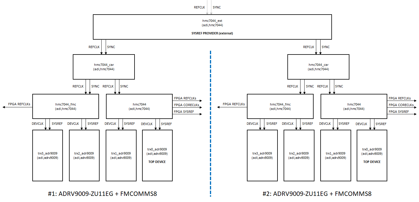
Synchronizing distributed multi-topology systems
In the example above let’s assume the left setup (#1) controls the top-level clock-chip (hmc7044_ext), which acts as the external SYSREF PROVIDER. We call this the PRIMARY setup. The right setup (#2) is therefore called SECONDARY.
The devicetrees for both of them can be found below. They include the above example and just add/remove pieces which are required to synchronize such a distributed Multi-Topology system.
#include "zynqmp-adrv9009-zu11eg-revb-adrv2crr-fmc-revb-sync-fmcomms8-jesd204-fsm.dts"
#include <dt-bindings/iio/frequency/hmc7044.h>
#include <dt-bindings/jesd204/device-states.h>

&trx0_adrv9009 {
    jesd204-stop-states = <
        JESD204_FSM_STATE_CLK_SYNC_STAGE1
        JESD204_FSM_STATE_CLK_SYNC_STAGE2
        JESD204_FSM_STATE_CLK_SYNC_STAGE3
        JESD204_FSM_STATE_LINK_SETUP
        JESD204_FSM_STATE_OPT_SETUP_STAGE1
        JESD204_FSM_STATE_OPT_SETUP_STAGE2
        JESD204_FSM_STATE_OPT_SETUP_STAGE3
        JESD204_FSM_STATE_OPT_SETUP_STAGE4
        JESD204_FSM_STATE_OPT_SETUP_STAGE5
        JESD204_FSM_STATE_CLOCKS_ENABLE
        JESD204_FSM_STATE_LINK_ENABLE>;
};

&hmc7044_car {
    jesd204-inputs = <&hmc7044_ext 0 FRAMER_LINK_RX>,
        <&hmc7044_ext 0 FRAMER_LINK_ORX>,
        <&hmc7044_ext 0 DEFRAMER_LINK_TX>;

    /delete-property/ jesd204-sysref-provider;
};

&hmc7044_ext {
    jesd204-device;
    #jesd204-cells = <2>;

    jesd204-sysref-provider;

    adi,pulse-generator-mode = <HMC7044_PULSE_GEN_1_PULSE>;
    adi,hmc-two-level-tree-sync-en;
};
On the devicetree for the PRIMARY device:
The hmc7044_ext device is added to the jesd204-fsm framework by adding the
jesd204-deviceproperty and connecting thejesd204-inputsof the hmc7044_car.The
jesd204-sysref-providermoves form the hmc7044_car to the hmc7044_ext device.The
jesd204-top-devicetrx0_adrv9009 now defines ajesd204-stop-statesarray. These are states in which the jesd204-fsm framework pauses (stops) and waits for some external resume event to occur.
#include "zynqmp-adrv9009-zu11eg-revb-adrv2crr-fmc-revb-sync-fmcomms8-jesd204-fsm.dts"
#include <dt-bindings/jesd204/device-states.h>

&trx0_adrv9009 {
    jesd204-stop-states = <
        JESD204_FSM_STATE_CLK_SYNC_STAGE1
        JESD204_FSM_STATE_CLK_SYNC_STAGE2
        JESD204_FSM_STATE_CLK_SYNC_STAGE3
        JESD204_FSM_STATE_LINK_SETUP
        JESD204_FSM_STATE_OPT_SETUP_STAGE1
        JESD204_FSM_STATE_OPT_SETUP_STAGE2
        JESD204_FSM_STATE_OPT_SETUP_STAGE3
        JESD204_FSM_STATE_OPT_SETUP_STAGE4
        JESD204_FSM_STATE_OPT_SETUP_STAGE5
        JESD204_FSM_STATE_CLOCKS_ENABLE
        JESD204_FSM_STATE_LINK_ENABLE>;
};

&hmc7044_car {
    /delete-property/ jesd204-sysref-provider;
    jesd204-secondary-sysref-provider;
};

&hmc7044_ext {
    status = "disabled";
};
On the devicetree for the SECONDARY device:
We must define exactly the same
jesd204-stop-statesat thejesd204-top-devicein this topology/setup.In addition, the
jesd204-sysref-provideris completely removed.And replaced by a
jesd204-secondary-sysref-providerattribute.
What is a secondary sysref-provider? An what is it used for?
A secondary sysref-provider is only used in distributed multi-topology systems. It’s purely used for JESD204 link (re-)establishment and not for other synchronization purposes.
The secondary sysref-provider, in case it exists, is only called if the jesd204-fsm device uses the jesd204_sysref_async_force() function.
Right now, this is done only in the driver for the axi_jesd204_rx link layer peripheral in case a link error interrupt is issued, or the watchdog detects an issue. The secondary sysref-provider is always assumed to be part of the JESD204 clocking tree. Furthermore, it is assumed that the SYSREF timer and frequency is already synced with the remaining part of the clocking tree.
In such situations the asynchronous request further down the clocking tree is never going to be an issue for JESD204 link bring-up and maintenance.
Why not always request SYSREF pulses next to the topology?
Well some more complex converter systems with internal NCOs and multi-chip sync
capabilities need synchronization events that are carried out across all devices
in a larger Multi-Topology system at the same instance in time. In such systems
the topology which controls the top-level clock distribution device registers
the primary sysref-provider. The jesd204-fsm jesd204-stop-states are used to
pause the device initialization and link bring-up in certain states.
Some external manager controls this and resumes the devices in a proper order.
What is an external manager?
Example: iio_jesd204_fsm_sync
This utility resumes a number of iio devices across different IIO context from the jesd204-fsm stop-states. It’s intended to sync multiple FPGA systems across jesd204-fsm topologies. There is always one primary device, the device which controls the sysref-provider and an open list of secondary devices which are synced by the same sysref-provider connected clock source. This utility exercises 5 IIO device attributes exposed by the TOP device.
IIO device attribute |
Comment |
|---|---|
jesd204_fsm_state |
reading returns the current state |
jesd204_fsm_error |
reading returns errno of previous state transition |
jesd204_fsm_paused |
reading 1 indicates that the FSM is currently paused/stopped |
jesd204_fsm_resume |
writing 1 resumes the topology from its current STOP state |
jesd204_fsm_ctrl |
writing 1 restarts the FSM |
Usage: iio_jesd204_fsm_sync -d <primary-device> -u <primary-uri> <secondary uris> ...
Example:
#iio_jesd204_fsm_sync -d adrv9009-phy -u ip10.48.65.140 ip:10.48.65.244
---------------------------------------------------------------------------
DEVICE0: adrv9009-phy uri=ip:10.48.65.140 (Primary) created
DEVICE1: adrv9009-phy uri=ip:10.48.65.244 (Secondary) created
---------------------------------------------------------------------------
DEVICE1: Is <Paused> in state <clk_sync_stage1> with status <Success (0)>
--- RESUME DEVICE1 ---
DEVICE0: Is <Paused> in state <clk_sync_stage1> with status <Success (0)>
--- RESUME DEVICE0 ---
---------------------------------------------------------------------------
DEVICE1: Is <Paused> in state <clk_sync_stage2> with status <Success (0)>
--- RESUME DEVICE1 ---
DEVICE0: Is <Paused> in state <clk_sync_stage2> with status <Success (0)>
--- RESUME DEVICE0 ---
---------------------------------------------------------------------------
DEVICE1: Is <Paused> in state <clk_sync_stage3> with status <Success (0)>
--- RESUME DEVICE1 ---
DEVICE0: Is <Paused> in state <clk_sync_stage3> with status <Success (0)>
--- RESUME DEVICE0 ---
---------------------------------------------------------------------------
DEVICE1: Is <Paused> in state <link_setup> with status <Success (0)>
--- RESUME DEVICE1 ---
DEVICE0: Is <Paused> in state <link_setup> with status <Success (0)>
--- RESUME DEVICE0 ---
---------------------------------------------------------------------------
DEVICE1: Is <Paused> in state <opt_setup_stage1> with status <Success (0)>
--- RESUME DEVICE1 ---
DEVICE0: Is <Paused> in state <opt_setup_stage1> with status <Success (0)>
--- RESUME DEVICE0 ---
---------------------------------------------------------------------------
DEVICE1: Is <Paused> in state <opt_setup_stage2> with status <Success (0)>
--- RESUME DEVICE1 ---
DEVICE0: Is <Paused> in state <opt_setup_stage2> with status <Success (0)>
--- RESUME DEVICE0 ---
---------------------------------------------------------------------------
DEVICE1: Is <Paused> in state <opt_setup_stage3> with status <Success (0)>
--- RESUME DEVICE1 ---
DEVICE0: Is <Paused> in state <opt_setup_stage3> with status <Success (0)>
--- RESUME DEVICE0 ---
---------------------------------------------------------------------------
DEVICE1: Is <Paused> in state <opt_setup_stage4> with status <Success (0)>
--- RESUME DEVICE1 ---
DEVICE0: Is <Paused> in state <opt_setup_stage4> with status <Success (0)>
--- RESUME DEVICE0 ---
---------------------------------------------------------------------------
DEVICE1: Is <Paused> in state <opt_setup_stage5> with status <Success (0)>
--- RESUME DEVICE1 ---
DEVICE0: Is <Paused> in state <opt_setup_stage5> with status <Success (0)>
--- RESUME DEVICE0 ---
---------------------------------------------------------------------------
DEVICE1: Is <Paused> in state <clocks_enable> with status <Success (0)>
--- RESUME DEVICE1 ---
DEVICE0: Is <Paused> in state <clocks_enable> with status <Success (0)>
--- RESUME DEVICE0 ---
---------------------------------------------------------------------------
DEVICE1: Is <Paused> in state <link_enable> with status <Success (0)>
--- RESUME DEVICE1 ---
DEVICE0: Is <Paused> in state <link_enable> with status <Success (0)>
--- RESUME DEVICE0 ---
---------------------------------------------------------------------------
--- DONE ---