1. How to assemble the AD-R1M hardware

1.1. Bill of Materials

AD-R1M Bill of Materials

Ref

Qty

P/N

Description

3D1

4

N/A

16 mm caster raiser

3D2

2

N/A

Motor mounts

3D3

2

N/A

3D printed camera mount brackets

3D4

1

N/A

3D printed camera housing

3D5

2

N/A

Wheel assembly

3D6

1

N/A

Electronics sub-assemblies mounting plate

3D7

1

N/A

3D Printed Front Panel

ADI1

2

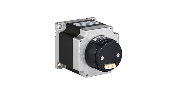
QSH5718-51-28-101-10K

NEMA 23 stepper motor 55Ncm, 2.8A

../../_images/qsh5718-51-28-101-10k.jpg

ADI2

1

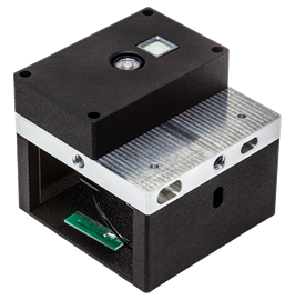
EVAL-ADTF3175D-NXZ

Time-of-Flight depth camera for perception

../../_images/eval_adtf3175.png

ADI3

2

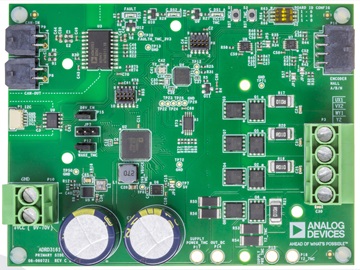
ADRD3161-01Z

Motor Control PCB

../../_images/adrd3161.jpg

ADI4

1

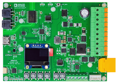
ADRD5161-01Z

BMS

../../_images/adrd5161.png

ADI5

1

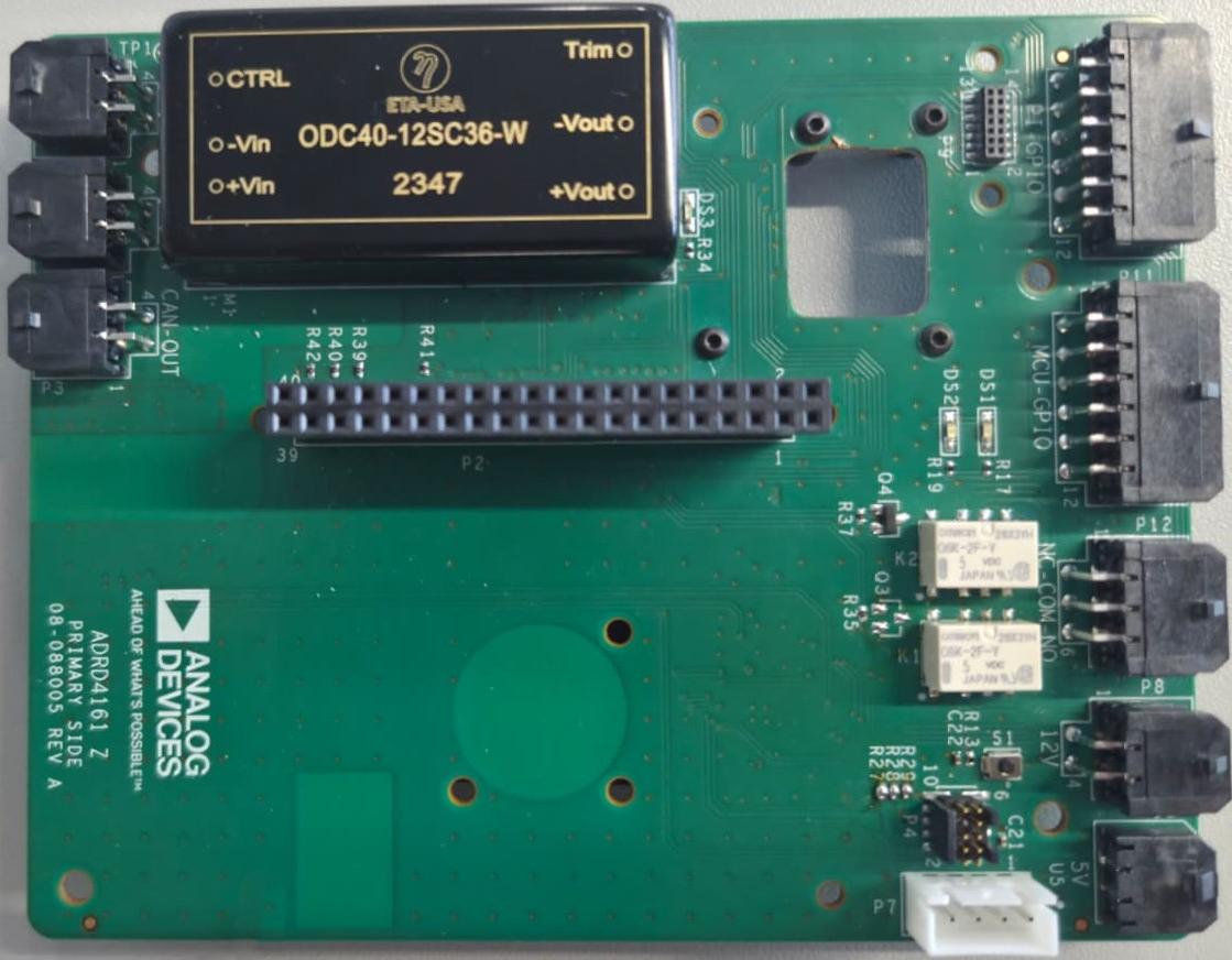
ADRD4161-01Z

Compute Carrier

../../_images/adrd4161_board.jpg

ADI6

1

N/A

Battery Holder

E1

1

RPi 5

Raspberry Pi 5 SBC

E2

1

IND16-12B-C

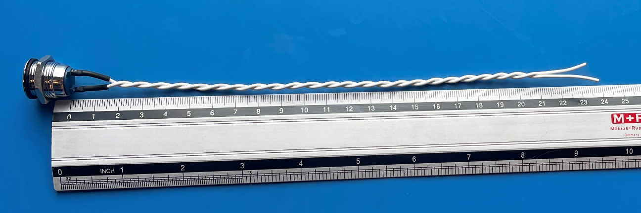
Status LED

E3

1

82-4151.1000

SPDT Button

E4

1

82-4151.1123

SPDT Button

M1

6

FA-093W201N05S01

Angle bracket

M2

6

A-094411M4

Panel holder

M3

1

K2020-I5 KRAFTBERG

340mm Aluminum 20X20 profile

M4

2

K2040-I5 KRAFTBERG

530mm Aluminum 20X40 profile

M5

1

K2040-I5 KRAFTBERG

340mm Aluminum 20X40 profile

M6

12

M5X8/D912-A4

Screw

M7

28

FA-096215

M5 Profile nut

M8

4

JDPE-0501-1001

Casters

M9

8

B5X25/BN3

M5 25mm screw

M10

8

B5/BN715

5mm washer

M11

8

B5X10/BN3

M5 10mm screw

M12

8

B5/BN161

M5 nut lock

M13

2

B4X8/BN3

M4 x 8 HEX

M14

2

B4/BN1074

M4 Washer

M15

8

M3X15/DR213

Standoff TFF

M16

4

M3X20/DR113

Standoff TFM

M17

8

M3X25/DR213

Standoff TFF

M18

16

M3X5/D7985

Screw

M19

16

B3X5/BN610

HEX Screw

M20

8

B5X16/BN3

M5 x 16 screw

1.2. Tools needed

Tools Required

Item

Description

Tape measure

For measuring frame dimensions and diagonals

Allen Key set

For tightening hex screws

Pliers

For general assembly

Crimping tools

For wire harness assembly

1.3. Assembly steps

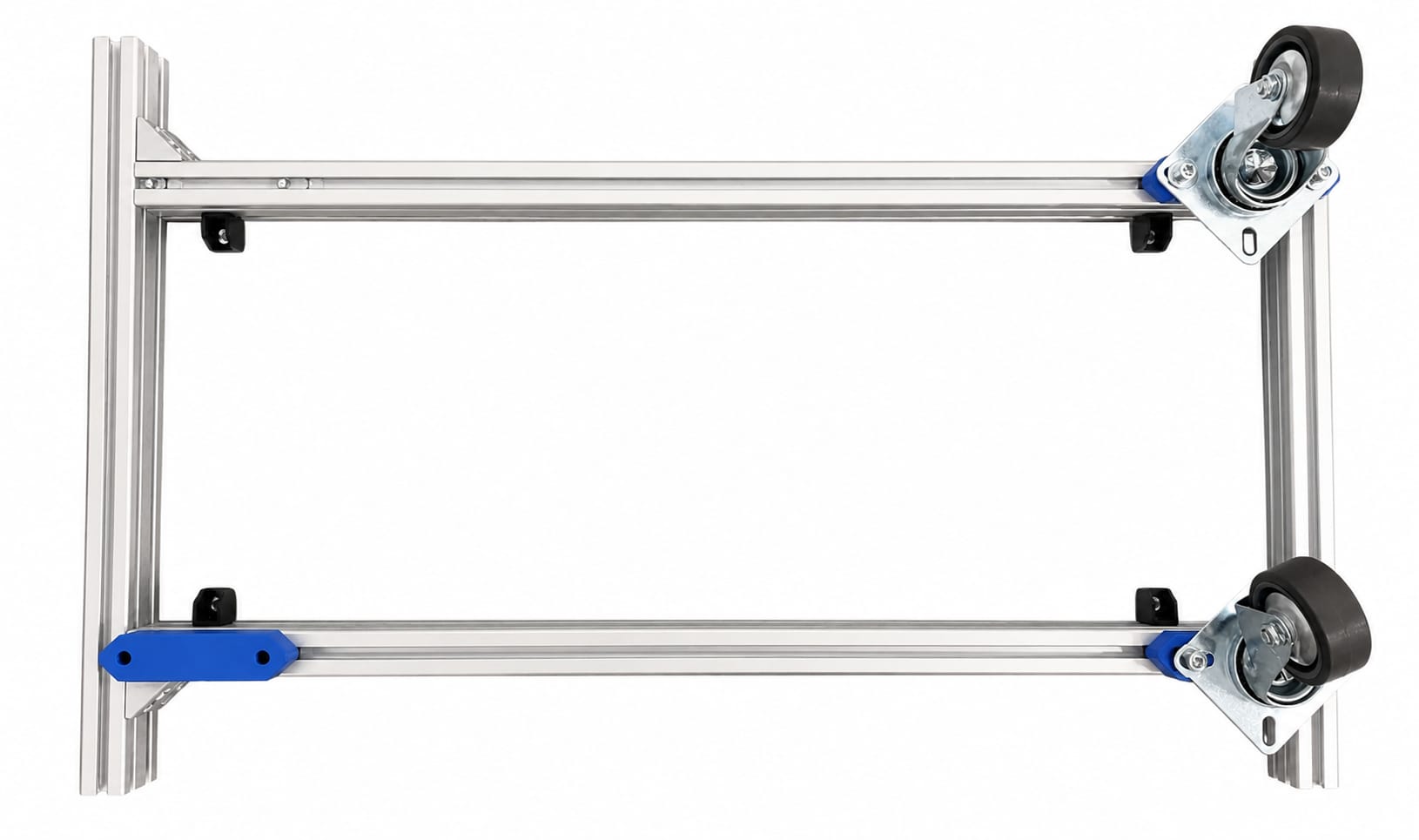
1.4. Frame

1.4.1. Step 1

Assemble the frame using the aluminum profiles and the angle brackets.

Make sure it results in a rectangular shape by measuring the diagonals.

Use 2 angle brackets to connect two K2040 profiles.

Place 4 “M2” holders 30mm away from the interior of the profile and 2 in the middle of the 530mm profiles.
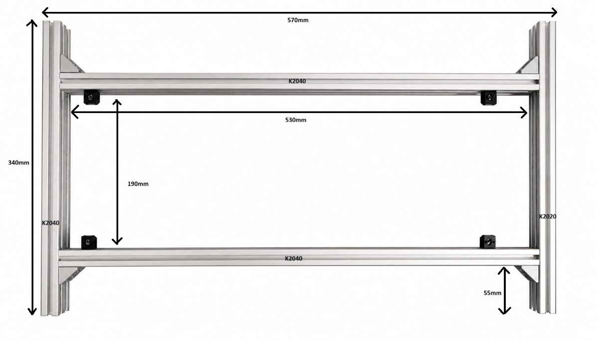
Frame Step 1 - Frame Assembly

Ref

Qty

P/N

Description

M1

6

FA-093W201N05S01

Angle bracket

M2

6

A-094411M4

Panel holder

M3

1

K2020-I5 KRAFTBERG

340mm Aluminum 20X20 profile

M4

2

K2040-I5 KRAFTBERG

530mm Aluminum 20X40 profile

M5

1

K2040-I5 KRAFTBERG

340mm Aluminum 20X40 profile

M6

12

M5X8/D912-A4

Screw

M7

12

FA-096215

M5 Profile nut

../../_images/image2.jpeg

1.4.2. Step 2

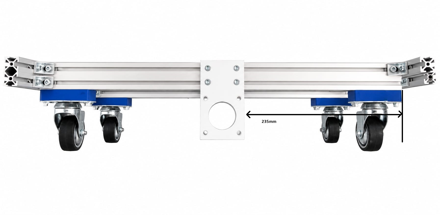
Place the wheels using the 3D printed 15mm caster raiser “3D1”.

Frame Step 2 - Wheels

Ref

Qty

P/N

Description

M8

4

JDPE-0501-1001

casters

3D1

4

N/A

16 mm caster raiser

M7

8

FA-096215

M5 profile nut

M9

8

B5X25/BN3

M5 25mm screw

M10

8

B5/BN715

5mm washer

../../_images/image3.jpeg

1.4.3. Step 3

Install the motor mounts “3D2”. The motor mounts need to be placed in the center of the 530mm longitudinal profiles.

Frame Step 3 - Motor Mounts

Ref

Qty

P/N

Description

3D2

2

N/A

Motor mounts

M7

8

FA-096215

M5 profile nut

M11

8

B5X10/BN3

M5 10mm screw

../../_images/image4.jpeg

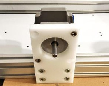
1.4.4. Step 4

Frame Step 4 - Motors

Ref

Qty

P/N

Description

M20

8

B5X16/BN3

M5 x 16 screw

M12

8

B5/BN161

M5 nut lock

ADI1

2

QSH5718-51-28-101-10K

NEMA 23 stepper motor 55Ncm, 2.8A

Install the motors.

../../_images/image5.png

1.4.5. Step 5

Install camera mounts 116.5 mm from the side 135.5 from camera.

Camera mounts and camera housing are 3D printed.
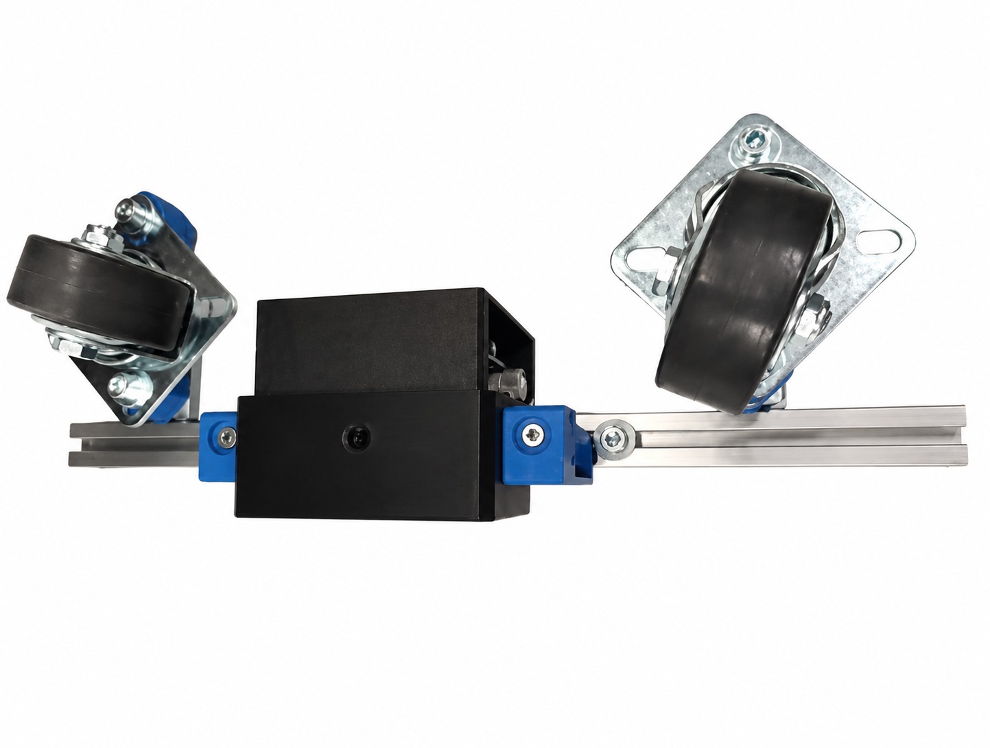
Frame Step 5 - Camera Mounts

Ref

Qty

P/N

Description

M13

2

B4X8/BN3

M4 x 8 HEX

M14

2

B4/BN1074

M4 Washer

3D3

2

NA

3D printed camera mount brackets

3D4

1

NA

3D printed camera housing

ADI2

1

EVAL-ADTF3175

Time-of-Flight depth camera for perception

../../_images/image6.jpeg

1.4.6. Step 6

Install the wheel assembly on the motor

Frame Step 6 - Wheel Assembly

Ref

Qty

P/N

Description

3D5

2

N/A

Wheel assembly

1.5. Electronic modules

1.5.1. Step 1

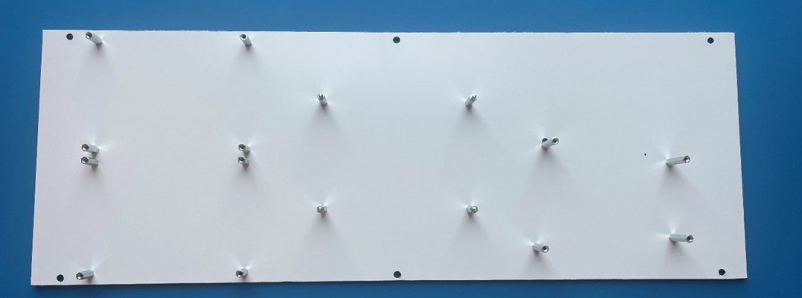
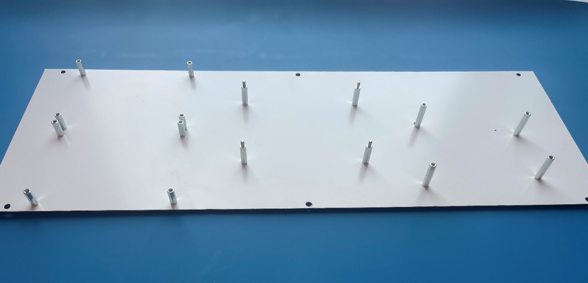
Place board spacers.

Electronics Assembly Step 1 - Spacers

Ref

Qty

P/N

Description

3D6

1

N/A

Electronics sub-assemblies mounting plate

M15

8

M3X15/DR213

Standoff TFF

M16

4

M3X20/DR113

Standoff TFM

M17

4

M3X25/DR213

Standoff TFF

M18

16

M3X5/D7985

Screw

../../_images/image7.png ../../_images/image8.png ../../_images/image23.png

1.5.2. Step 2

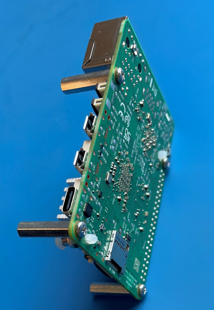
Place PCB sub-assemblies.

The BMS board goes above the battery holder on 4 M3X25 standoffs.
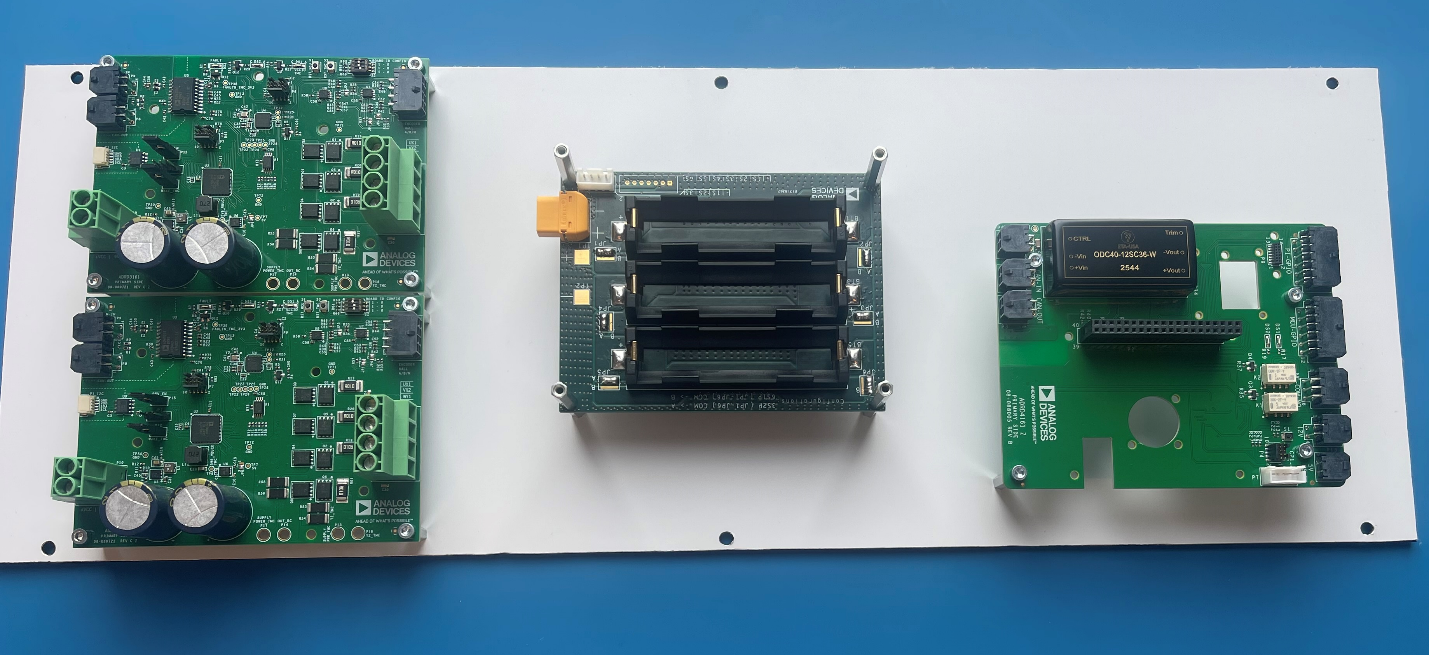
Electronics Assembly Step 2 - Boards

Ref

Qty

P/N

Description

M19

16

B3X5/BN610

HEX Screw

M17

4

M3X25/DR213

Standoff TFF

ADI3

1

ADRD3161

Motor Control PCB

ADI4

1

ADRD5161

BMS

ADI5

1

ADRD4161

Compute Carrier

ADI6

1

N/A

Battery Holder

E1

1

RPi 5

Raspberry Pi 5 SBC

../../_images/image9.png

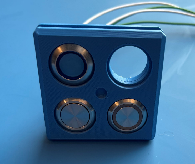
1.6. Control Panel

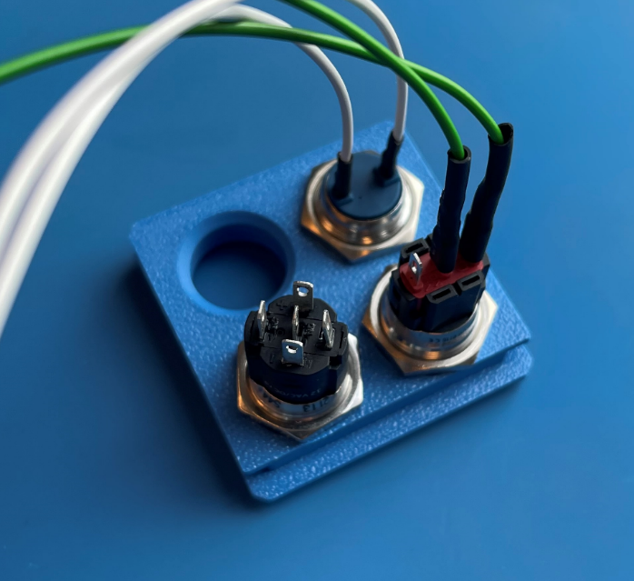
Control Panel Components

Ref

Qty

P/N

Description

E2

1

IND16-12B-C

Status LED

E3

1

82-4151.1000

SPDT Button

E4

1

82-4151.1123

SPDT Button

3D7

1

N/A

3D Printed Front Panel

../../_images/image10.png ../../_images/image11.png

1.7. Wiring Harness

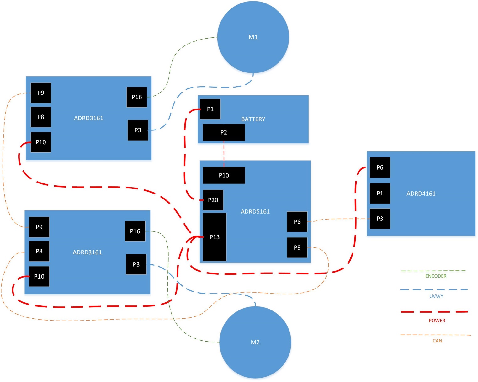
Main wiring diagram:

../../_images/image12.jpeg ../../_images/image13.png

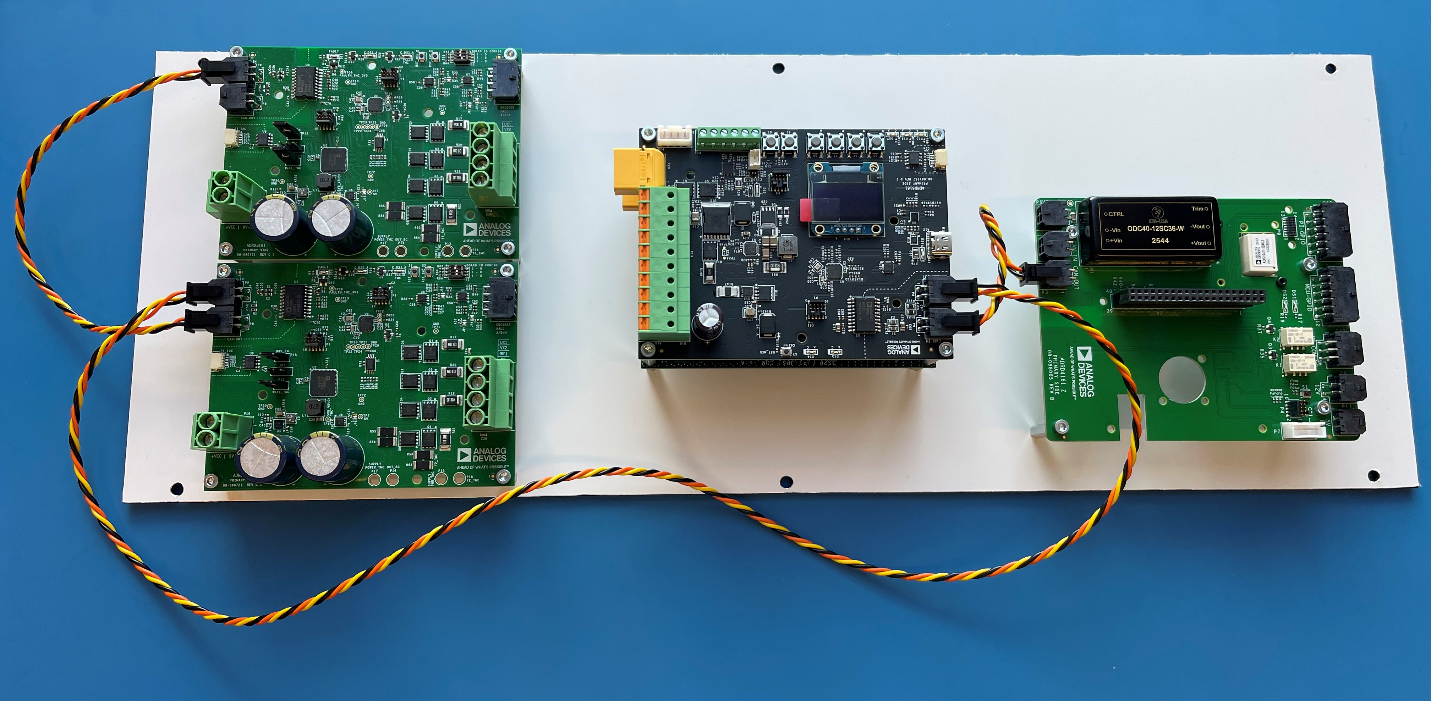
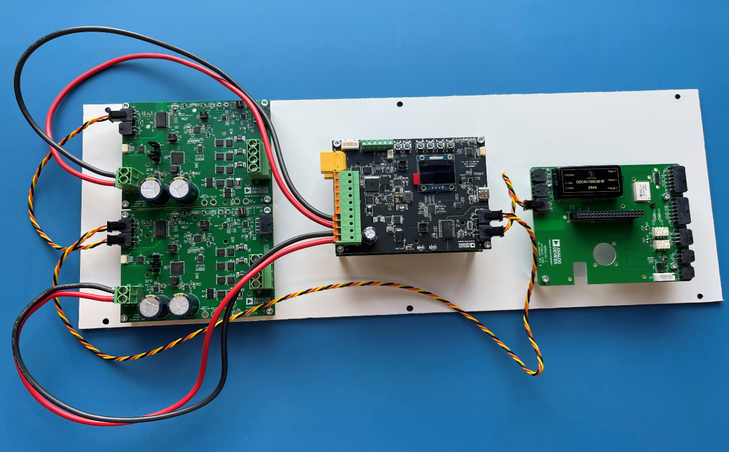
Wiring steps:

../../_images/image14.png ../../_images/image15.png ../../_images/image16.jpeg

Wire assemblies:

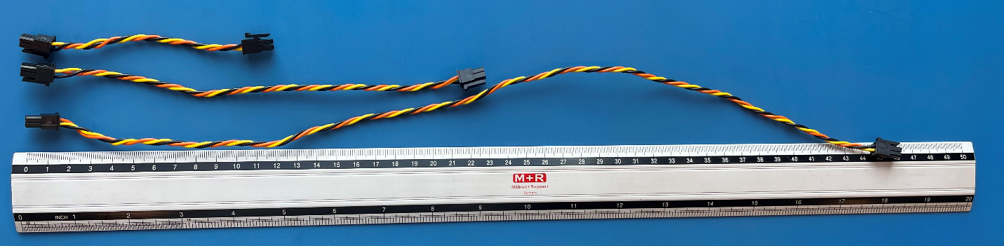
1.7.1. CAN

Twisted pair + GND with Molex Micro-Fit 3.0 43025-0400 connectors on both sides.
../../_images/image17.png

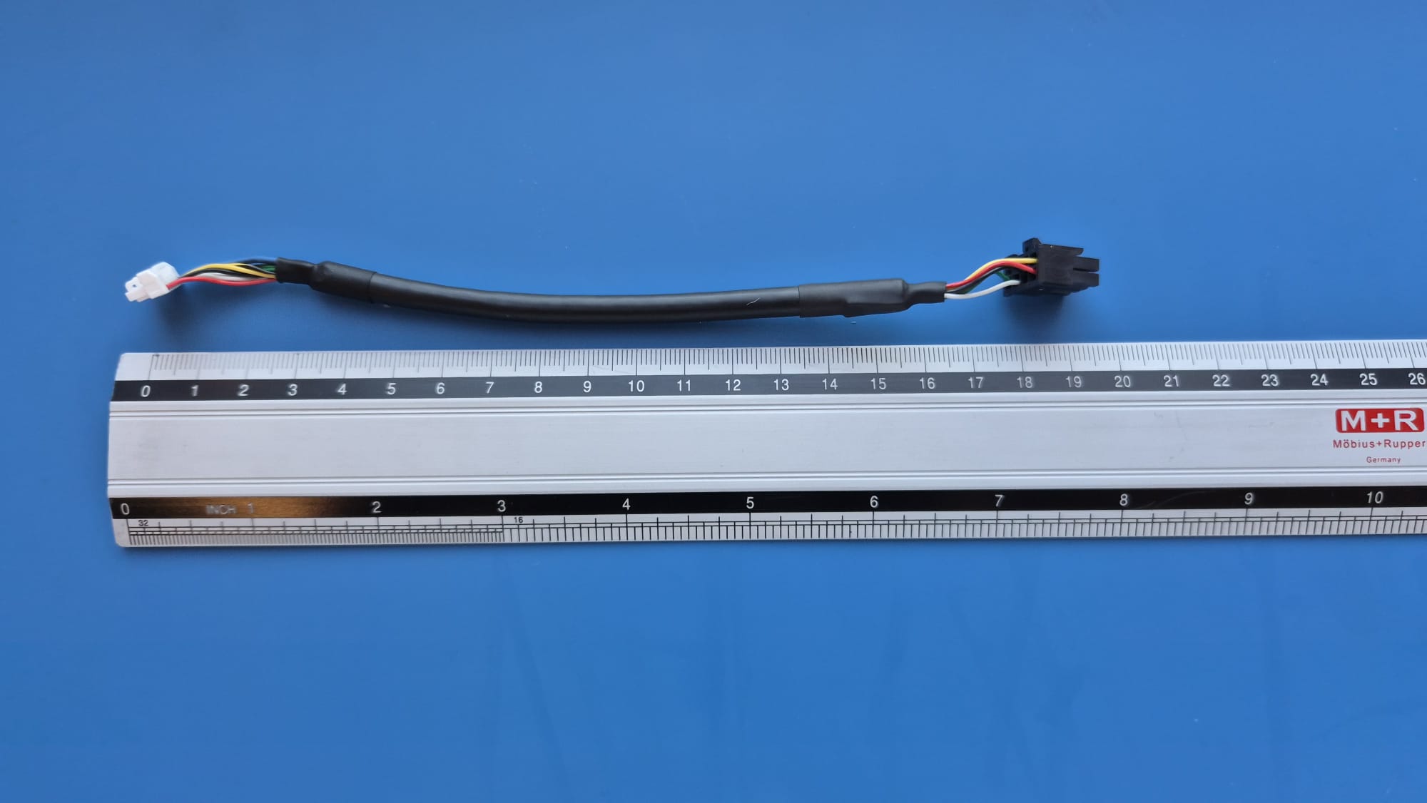
1.7.2. Motor encoder

Wire assembly with Molex Micro-Fit 3.0 43025-0800 connector on the motor control board side. For more details check ADRD3161 documentation.
../../_images/image18.jpeg

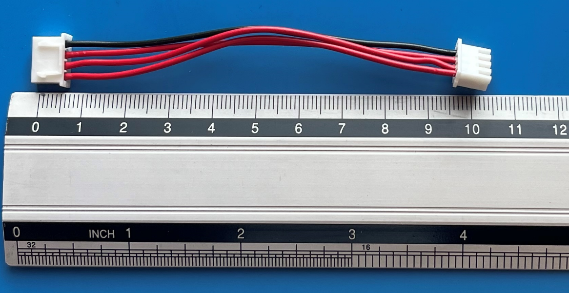
1.7.3. Battery balancing

Wire assembly, 4 wires with JST XHP-4 connectors on both sides.
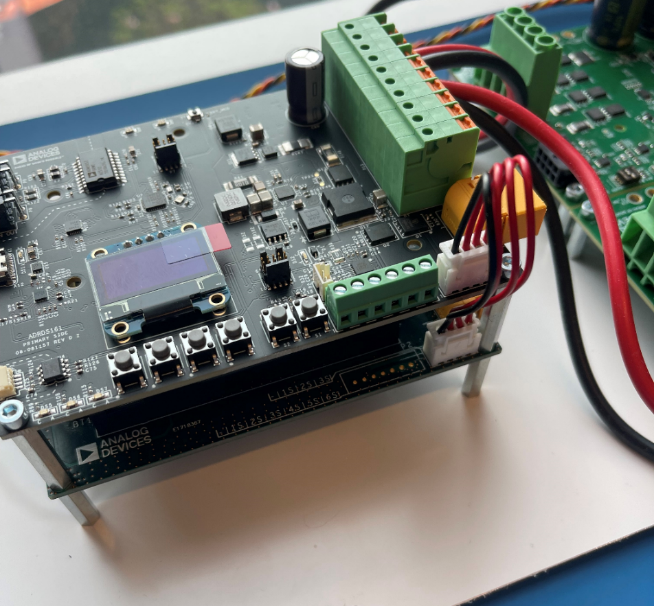
../../_images/image19.png ../../_images/image20.jpeg

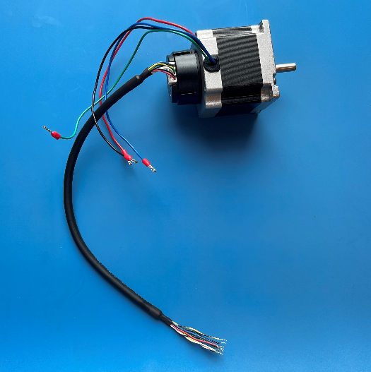
1.7.4. Power wires

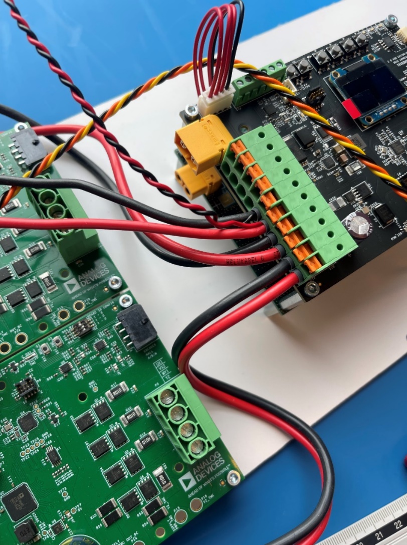
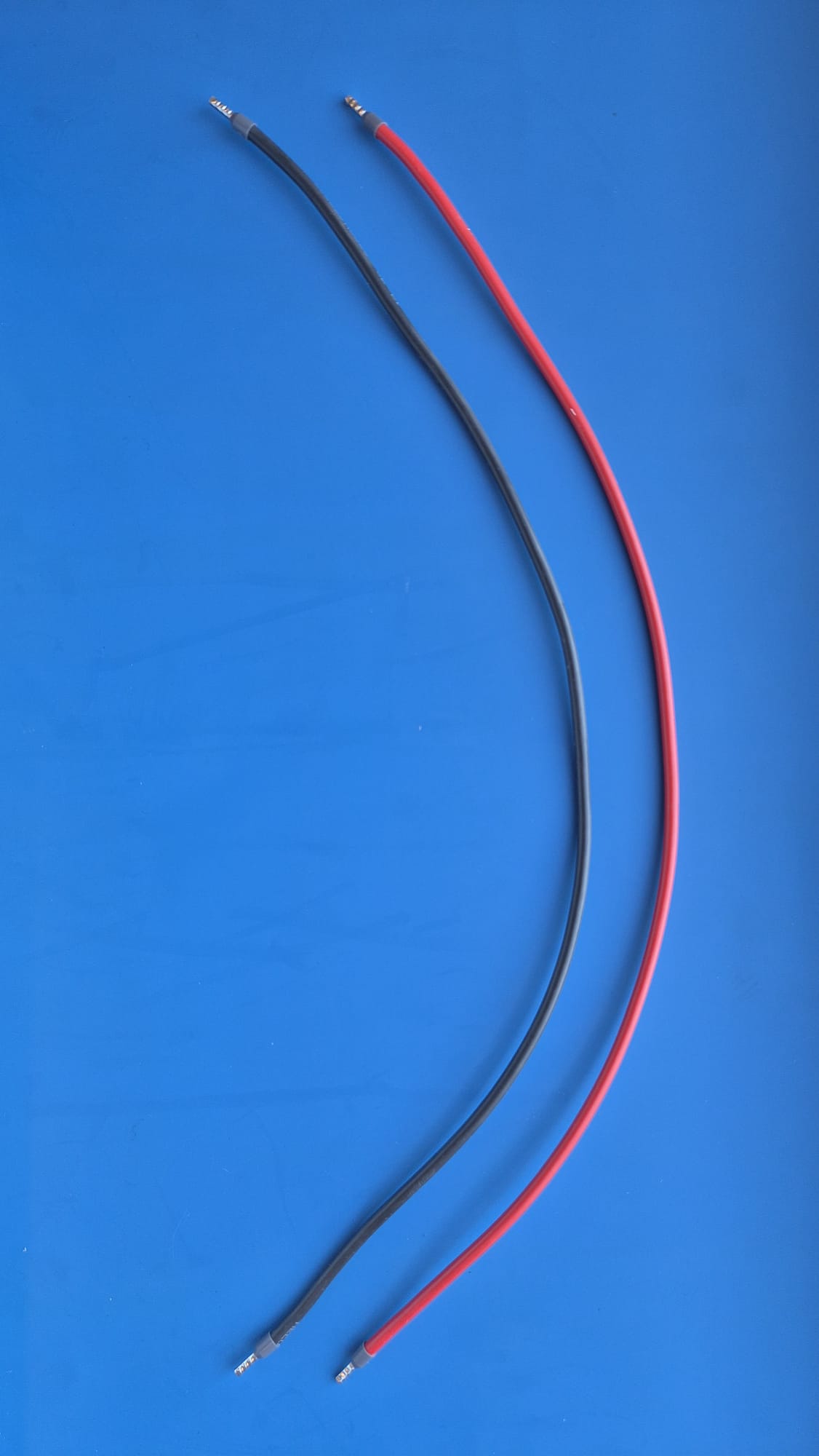
  • 2.5mm wires with bootlace ferrule.

  • 450 mm length from the BMS to the motor control board, 2 pairs.
../../_images/image21.png ../../_images/image22.png ../../_images/image24.png ../../_images/image25.png ../../_images/image26.png