Receiving and Sending Data
Remote data streaming to and from hardware is made available through system object interfaces, which are unique for each component or platform. The hardware interfacing system objects provide a since class to both configure a given platform and move data back and forth from the device.
Command and control of hardware from MATLAB is accomplished by leveraging the IIO drivers built into the target platform's kernel and libiio which provides remote backends to control drivers across different backends. Backends can be Ethernet, serial, or USB based. Below is a diagram of the different components in the stack for an FMComms based systems, but will be nearly identical for all transceiver based systems.
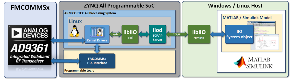
Since libiio is cross-platform it can be used from Windows, Linux, or macOS based systems. It is also a lower level library independent of MATLAB, so when moving toward production or untethered systems similar APIs that are used in MATLAB can be used in C,C++,Python, or other languages.
Connecting and Configuration
Connecting to hardware is done by setting the uri property of the system object interface. The uri for libiio always has the convention "< backend >:< address >", where backend can be ip,usb, or serial. address will be specific to the backend. This is documented in the libiio API.
Below is a basic example of setting up an AD9361 receiver using an Ethernet/IP backend where the address of the target system is 192.168.2.1:
With the code above, the hardware is not contacted until the operator or step method is called on line 3. Therefore, any properties that are set or defined before line 3 are not applied or updated on the hardware until after line 3. However, after line 3 has completed the object will become locked and certain configuration changes cannot be applied after this point. These will primarily sample rates and buffer sizes.The state of the object follows the flow of the diagram below triggered by line 3 above.
To provide a complete example we can do more advanced configuration like so to demonstrate property changes:
Receiving Data
To receive or capture data from a given device first you must instantiate that device's interface class. For example on a DAQ2 based system, this would be as follows:
Once instantiated you can configure the number of samples to be captured by setting the property SamplesPerFrame.
SamplesPerFrame is the number of samples per channel which will be captured. If your device produces complex data (I and Q) this is the number of complex samples. There will be a limit to the maximum samples which can be collected. By default this is set to 2^20, but it may be possible to make it larger depending on hardware. Once the operator methods are used for a give instantiation, the object will become locked and the SamplesPerFrame property cannot be changed. This is known as a non-tunable property.
To actually collect the samples or perform the capture, the operator of the system object should be used or the step method as so:
Both method calls are equivalent, and the produced matrix data will be of size [SamplesPerFrame x length(EnabledChannels)]. EnabledChannels determines the channels which data will be collected from. EnabledChannels is a [1xN] vector with indexes starting at 1 of the desired channels. If the device transmits or receive complex data, these indexes are for complex channel pairs. For example, the AD9081 can have 16 complex channels from 4 ADCs and setting EnabledChannels as so will capture data from all 16 converters:
You cannot enable individual converters on complex data based devices, and the EnabledChannels property is always sorted so the channel mappings cannot be changed within the produced data.
Sending Data
Transmitting data is very similar to receiving it, a transmitter class needs to be instantiated to send data first. For an AD9081 based device this would be as follows:
Unlike the receivers, transmit objects automatically create their internal buffers based on the data passed to them during their operator or step methods. These methods can be called as follows with some data:
tx_data = complex(2^15.*randn(1024,1),2^15.*randn(1024,1));
tx(tx_data); % Operator method
tx.step(tx_data); % Step method
However, once the step or operator method is called the object becomes locked and future passed data vectors must be the same length. As with the receive classes, the size of the passed data must be [SomeFixedSize x EnabledChannels]. EnabledChannels has the same definition as the receive side, except applied to DACs.
Unlike the receiver, transmit objects have the ability to utilize cyclic buffers which will continuously transmit a provided vector without gaps forever. To utilize cyclic buffers set the EnableCyclicBuffers property then pass the operator data as follows:
tx = adi.AD9081.Tx;
tx.EnableCyclicBuffers = true;
tx_data = complex(2^15.*randn(1024,1),2^15.*randn(1024,1));
tx(tx_data); % Data will repeat forever
Once a vector is passed to the object with EnableCyclicBuffers set to true, the object will not accept future buffers unless first release or cleared.
By default the system objects will utilize DMA as the source of data for the DACs, which will use data past from the operator. This can be set manually through the DataSource properties as follows:
DDS
Instead of providing data for transmission, it is possible to utilize DDSs inside the FPGA to send tones to individual DACs. For specific boards there are two DDS per DAC, which can be used to create complex (one-sided) tones. These DDSs can be used by first setting the DataSource property:
Then the scale, frequency, and phase of each DDS can be controlled through three attributes as follows:
rx.DDSFrequencies = [1e3,1e3,1e3,1e3;1e4,1e4,1e4,1e4]; % Must be range [0 FS/2]
rx.DDSScales = [1,1,1,1;0,0,0,0]; % Must be range [0,1]
rx.DDSPhases = [0,90e3,0,90e3,0,0;0,0,0,0]; % Each in millidegrees [0,90000]
Each of the above properties must be of size [2x(NumberOfPartDACs)], where each row is the first DDS of a given DAC (column) and the second row is the second DDS of a given DAC (column).