User Guide

Hardware Guide

Board Overview

https://media.githubusercontent.com/media/analogdevicesinc/documentation/admx100x/docs/solutions/reference-designs/admx100x_evb/images/eval-admx100x-fmcz_evaluation_board.png

Figure 1 EVAL-ADMX100X-FMCZ Evaluation Board

https://media.githubusercontent.com/media/analogdevicesinc/documentation/admx100x/docs/solutions/reference-designs/admx100x_evb/images/admx100x_module.png

Figure 2 ADMX100X Module

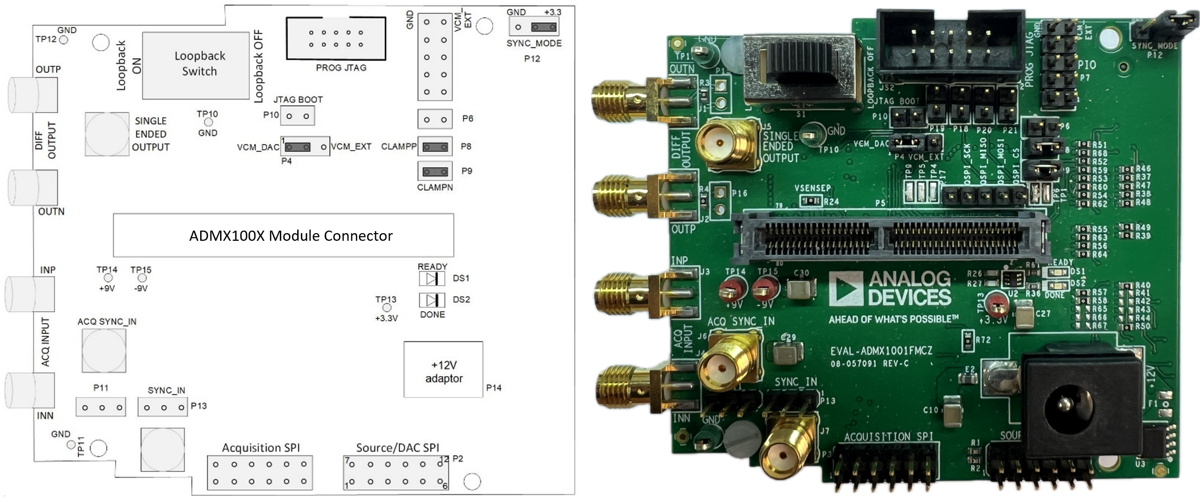
The EVAL-ADMX100X-FMCZ evaluation board provides the following connectors:

  • P1: FMC connector for SDP-H1 connection

  • P2: PMOD header for SDP-I-PMOD interposer connection (SDP-S/SDP-B)

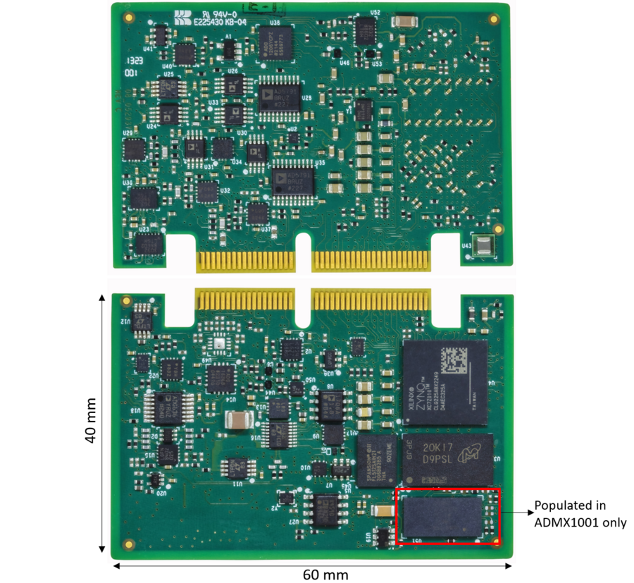
  • P5: Module connector for ADMX100X module

  • SYNC_IN / SYNC_OUT: SMA connectors for coherent sampling synchronization

  • Output SMA connectors for signal measurement

Table 1 Table 1. SMA Connector Descriptions

Connector

Description

OUTP

Source positive output

OUTN

Source negative output

SINGLE ENDED OUTPUT

Source single-ended output

INN (ADMX1001 only)

Acquisition channel negative input

INP (ADMX1001 only)

Acquisition channel positive input

ACQ_SYNC_IN (ADMX1001 only)

Acquisition channel sync input

SYNC_IN

Source input sync clock

SYNC_OUT

Source output sync clock

Jumper and Switch Configuration

Verify the jumper and switch settings before powering the board.

Table 2 Table 2. Jumper and Switch Setup

Name

Function

Default Position

P4

VCM source: 2-1 = VCM from DAC, 2-3 = external VCM

2-1 (VCM_DAC)

P6

EN control

Removed

P8

Sense input clamp to +5 V

Inserted

P9

Sense input clamp to −5 V

Inserted

P10

JTAG_BOOT

Removed

P11

ACQ_SYNC_IN

Removed

P12

SYNC_MODE: 2-1 = +3.3 V (internal), 2-3 = GND (external)

2-1 (+3.3 V)

P13

SYNC_IN

Removed

S1

Signal loopback enable

Loopback Off

Schematic, PCB Layout, Bill of Materials

Design files for the EVAL-ADMX100X-FMCZ evaluation board are available on the EVAL-ADMX100X-FMCZ product page.

Software Guide

Installing SDP USB Drivers

https://media.githubusercontent.com/media/analogdevicesinc/documentation/admx100x/docs/solutions/reference-designs/admx100x_evb/images/installation_wizard_welcome.png

Figure 3 SDP Driver Installation Wizard

The SDP USB drivers must be installed before the ADMX100X GUI.

  1. Download the SDP USB drivers from the Analog Devices website.

  2. Run the driver installer and follow the on-screen instructions.

  3. Accept the license agreement, select the install location, and click Install.

  4. Reboot the PC if prompted.

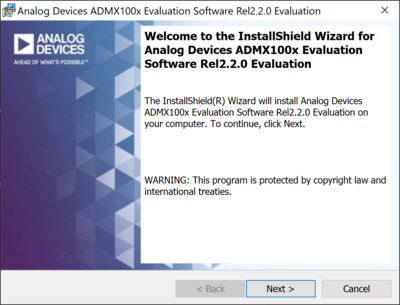
Installing the ADMX100X GUI

  1. Download the ADMX100X GUI evaluation software from the EVAL-ADMX100X-FMCZ product page.

  2. Run the installer and follow the on-screen instructions.

  3. Launch the ADMX100X GUI from the Start menu after installation.