AD9371/AD9375 IIO Oscilloscope
ADI IIO Oscilloscope
The IIO Oscilloscope is a cross-platform application for interfacing with IIO devices, enabling you to configure device parameters and visualize data.
Important
Make sure to download/update to the latest version of IIO Oscilloscope.
For Linux
Remote run on host
The IIO Oscilloscope application can be used to connect to another platform that has a connected device, to configure the device and read data from it. This application is not for performance testing, but rather showcasing the basic features.
Please see IIO Oscilloscope documentation for installation steps and more details.
Build and start osc on a network-enabled Linux host.
For Windows computers, open the application from the start menu.
Once the application is launched, go to Settings > Connect > URI and type “ip:” then the IP address of the target in the pop-up window. This IP can be found out with a command from the previous section of this documentation.
For no-OS
For connecting IIO Oscilloscope to no-OS applications, they need to be built with the IIOD=y flag. This way, the no-OS applications will run an IIO daemon that is awaiting connections from the IIO Oscilloscope.
As indicated in the boot log, the board runs an IIOD server over the serial (UART) connection.
Disconnect or close the serial terminal used to view the boot log.
Once done with the installation or an update of the latest IIO Oscilloscope, open the application.
Select the Serial backend and configure the connection with the settings shown at the end of the boot log.
Press Refresh to display the available IIO devices and press Connect.
Note
The serial port is the COM port on Windows or /dev/ttyUSBx on Linux.
Plugin
This project also contains an IIO-Oscilloscope device-specific plugin that enables you to access the unique features and functions of the device.
See also
For more information about this plugin: AD9371/AD9375 Plugin Description
Channel Description
Main receivers RX1 and RX2 are handled by the axi-ad9371-rx-hpc IIO device, while the observation is handled by the axi-ad9371-rx-obs-hpc device.
Channels:
Receiver Inputs |
||
|---|---|---|
IIO Device Channels |
voltage0_i voltage0_q |
voltage1_i voltage1_q |
axi-ad9371-rx-hpc |
RX1 |
RX2 |
axi-ad9371-rx-obs-hpc |
OBS RX1 |
Data capture
Note
Device names and channel definition may differ between no-OS and Linux.
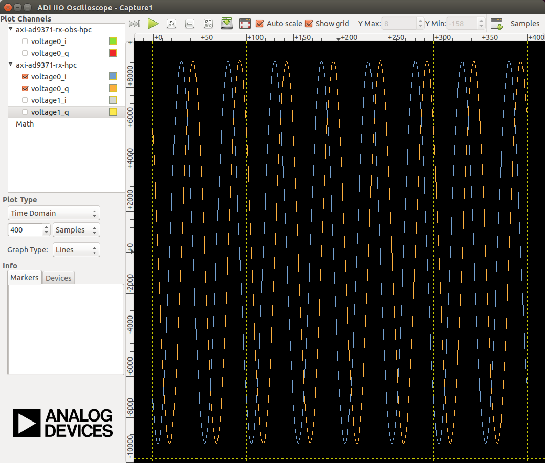
Time domain:
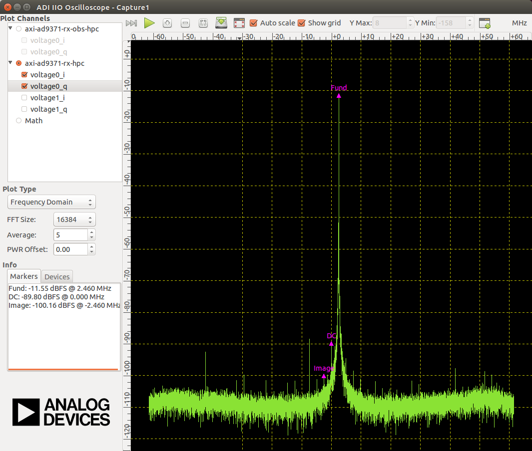
Frequency domain: