AD5770r Console Application
Supported Hardware
Supported Devices:
Supported Evaluation Boards:
Supported Carrier Boards:
Introduction
The AD5770R is a 6-channel, 14-bit resolution, low noise, programmable current output digital-to-analog converter (DAC) for photonics control applications. This chip incorporates a 1.25 V on-chip voltage reference, a 2.5 kΩ precision resistor for reference current generation, die temperature, output monitoring functions, fault alarm, and reset functions.
The AD5770R contains five 14-bit resolution current sourcing DAC channels and one 14-bit resolution current sourcing/ sinking DAC channel.
Channel 0 can be configured to sink up to 60 mA and source up to 300 mA. Channel 1 to Channel 5 have multiple, programmable output current sourcing ranges, set by register access. Each DAC can operate with a wide power supply rail from 0.8 V to AVDD − 0.4 V for optimizing power efficiency and thermal power dissipation.
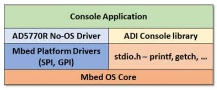
This page describes the AD5770R firmware example running on the SDP-K1 controller board, interfacing with the AD5770R evaluation board. The firmware example comprises 3 layers of software, It can support STM32 platform.
Console Application - uses the ADI console libraries to provide a basic terminal UI
AD5770R No-OS Driver - AD5770R device C API
Platform Drivers - Hardware Abstraction Layer (SPI, GPIO, …) to adapt No-OS driver
The AD5770R firmware example can be used as a starting point for developing your own code in your own environment. The Platform simplifies the overall software development process by providing a common low level driver abstraction. This reduces the hardware dependency on any STM32 board can be used with same firmware with little to no modifications, usually just changing the pin mapping.
Interface Diagram
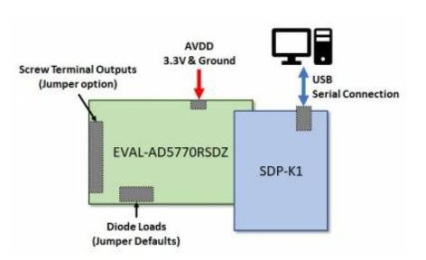
The AD5770R Evaluation Board is connected to SDP-K1 using the 120-pin SDP Connector. The evaluation board must be powered externally, typically using an external 3.3V DC supply connected to the AVDD input supply terminal, if using the default power supply jumper settings.
The SDP-K1 is connected to a PC through a USB cable. The firmware image, a .BIN file created using the online mbed compiler, can be loaded into SDP-K1 board by copying the .BIN file to the drive representing the SDP-K1. The SDP-K1 provides a USB to Serial link (UART) and any serial terminal (such as Teraterm, Putty, Coolterm, etc) can be used to connect to by configuring terminal with the necessary settings (serial port, baud rate, data bits, etc).
Note
Connect the VIO_ADJUST jumper on the SDP-K1 board to 3.3V position to drive SDP-K1 GPIOs at 3.3V
Useful Links
Note
Linux and HDL are not used in emebdded IIO firmware projects but they may be of interest if you require Linux and/or FPGA support.
Build Guide
Build Prerequisites
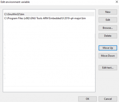
Prior to building a firmware project, it is required to set up an environment so that the build process may find the necessary tools (compiler, linker, SDK etc.). Use the following steps to prepare your environment for building firmware projects for respective platform.
Clone Precision Converters Firmware repository with the –recursive flag:
git clone --recursive https://github.com/analogdevicesinc/precision-converters-firmware
If however you’ve already cloned the repository without the –recursive flag, you may initialize all the submodules in an existing cloned repo with:
git submodule update --recursive --init
Install STM32CubeIDE
Install STM32CubeMX
Building a project
Once the build enviornment is setup, follow the guide below to build your project and generate executable file (.bin/.hex)
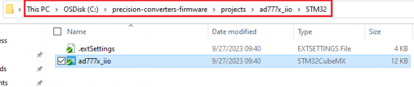
Open the respective project directory by navigating into the “precision_converters_firmware/projects/” folder.
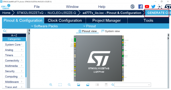
In the “STM32” folder present within the project directory, double click and open the .ioc file present within.
Click on the “Generate Code” option seen on the top right corner
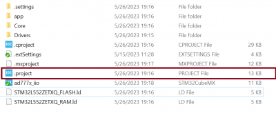
Upon successful generation of drivers for the selected MCU, the autogenerated files would be seen in the same directory where the .ioc file was present. Double click and open the “.project” file seen in the list of files
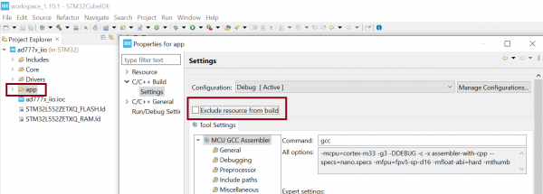
After the project is loaded to the STM32CubeIDE, unfold the adxxxx_iio project seen in the project explorer, right click the “app” folder, select “Settings” under the “C/C++ Build” section on the left pane and un-check the “Exclude resources from build” checkbox. This would ensure that the project specific files are included by the build system
Add compiler flags “-u _printf_float” to the project settings.
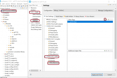
Exclude the generated file syscalls.c from the build process

- To generate the binary file, right click on the adxxxx_iio project seen in the project explorer and select “Properties”, select “Settings” under the “C/C++ Build” section on the left pane, select “MCU Post build outputs” under “Tool Settings” section and check the “Convert to binary file (-O binary)” checkbox.

Build the project by right-clicking on the adxxxx_iio project seen in the project explorer and select “Build Project”

Running a project
Once the firmware build is successful and binary file is generated, copy the generated binary into USB drive hosted by your MCU board (e.g. USB drive hosted by MCU board on windows). This will flash the binary file into MCU present on the controller board. Programming might vary based on the tools used for building a project. The ‘Project Build’ section above talks about this exception at the end of all build steps.
Quick Start
If you have some familiarity with the STM32 platform, the following is a basic list of steps required to start running the code, see below for more detail:
Connect the evaluation board to the SDP-K1 controller board, and power it appropriately, usually 3.3V to AVDD.
Connect the SDP-K1 controller board to your computer over USB.
Follow the steps mentioned in the Build Guide section above.
- Start up a serial terminal emulator (e.g. Tera Term)
Find the com-port your controller board is connected on and select it.
Set the baud-rate for 230400
Reset the controller board and connect.
The terminal windows should display the console menu providing access to the AD5770R functionality.
Using the Firmware
The example is menu driven, providing keyboard shortcuts to access/execute the menus items, and prompting for further inputs where necessary. When the example runs, it attempts to connect and initialize the AD5770R. The configuration used is defined in the ad5770r_user_config.h file, which can be modified as needs be to suit specific applications.
Note
While much of the functionality of the AD5770R No-OS driver is made available through the console UI, not all function are available. The additional AD5770R functionality can only be configured the ad5770r_user_config.c file.
Main Menu
The AD5770R Console App main menu provides basic initialization/reset type functions, and access to several sub-menus that provide more detailed configuration and control settings. Like most menus in the firmware, the menu options are framed by a header and footer that display status information related to the functions on the menu.
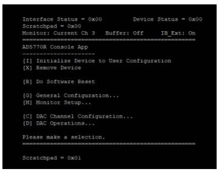
The value of the scratchpad register is displayed in both the header and the footer. After reading the scratchpad value for the header, the value is incremented and written back to the device, such that the scratchpad footer value should always be equal to the header value + 1. This can be useful a debug aid to confirm communications.
DAC Operaions
This menu provides the ability to set the Input and DAC register values, and control the update of the DAC using both the hardware and software LDAC functions. The ordering of menu items is intended to follow the order in which actions are typically performed by the user.
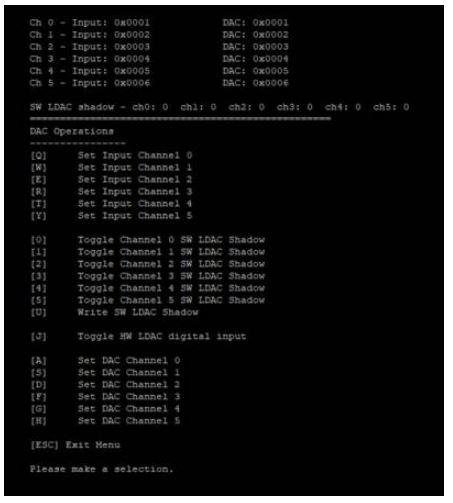
There are three ways in which the DAC output may be controlled using this menu.
Write to Input Channel(s), set software LDAC shadow value, then write software LDAC to update DAC output
Write to Input Channel(s), toggle hardware LDAC
Write to DAC Channel to directly update DAC output
Toggling a channel in the software LDAC shadow sets a bit corresponding to that channel in a mask. This SW LDAC Channel shadow value can then be written in a single transaction, transferring the input to the DAC value for all of the channels which are set in the shadow mask.
The channels affected by the hardware LDAC pin toggling are set in the ad5770r_user_config.h file at compile time.
Note
The toggling of the hardware LDAC is outside of the AD5770R No-OS driver, and as such the DAC values are not updated by this action.
Support
Feel free to ask questions in the EngineerZone