LTC268x Console Application
Supported Hardware
Supported Devices:
Supported Evaluation Boards:
Supported Carrier Boards:
Introduction
The LTC2686/8 are 8/16-channel, 16-bit, ±15 V digital-to-analog converters (DAC) with an integrated precision reference. The LTC268X example software can be used as a starting point for developing your own code for Analog Devices DC2873A-B or DC2904A board in your own environment. This guide will focus interfacing the DC2873A-B or DC2904A-B evaluation board with Analog Devices SDP-K1 controller board or an STM32 board. The firmware example comprises 3 layers of software (from top to bottom): Console Application Layer, Device No-OS Layer and Platform Drivers layer.It supports STM32 platform.
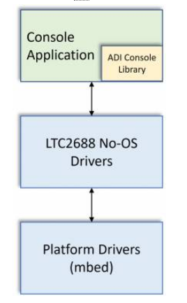
The application layer uses the ADI Console Libraries to create console-based User Interactive (UI). The middle layer of No-OS device library has device specific APIs to interface with LTC2686/8 devices. These APIs allows direct access to device register map in order to read/write device registers. The bottom layer of Platform Drivers is responsible for Low Level Interface. The platform drivers use underlying libraries to access low level peripheral (like GPIOs, SPI, I2C, etc). The devices from LTC2686/8 family use SPI communication interfaces respectively.
This guide focuses on the SDP-K1, connected to the DC2873A-B or DC2904A-B board, but it should be general enough to cover any compatible controller board (the controller board should expose at least SPI or I2C and some GPIO’s). The Platform simplifies the overall software development process by providing the low level driver support. This reduces the hardware dependency as an STM32 board can be used with same firmware with little modifications (precisely changing a pin mapping).
The software described below allows an STM32 controller board to be connected with an Analog Devices evaluation board. Unmodified, the code will communicate over any serial terminal emulator (CoolTerm, putty, etc) using the UART provided by the controller board over USB.
Interface Diagram
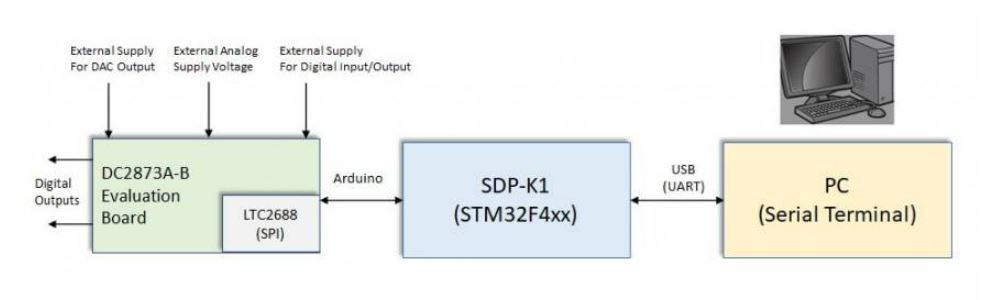
The DC2873A-B/DC2904A-B evaluation board is connected to SDP-K1 using the Arduino Headers and jumper wires. The DC2873A-B/DC2904A-B evaluation board VCC and IOVCC can be powered-up through a SDP-K1 USB supply or from external DC supply using the turrets connection. The SDP-K1 is connected to PC through an USB cable. The firmware (binary executable) can be loaded into SDP-K1 board through this USB interface from the PC. The SDP-K1 acts as a Serial Device (UART) and firmware loaded into it interacts with any serial terminal (like Teraterm, Putty, Coolterm, etc) by configuring terminal for proper serial settings (COM Port, Baud Rate, data bits, etc)
Useful Links
Note
Linux and HDL are not used in emebdded IIO firmware projects but they may be of interest if you require Linux and/or FPGA support.
Hardware Connections
The DC2873A-B/DC2904A-B evaluation board can be connected to the SDP-K1 using jumper wires from the Arduino header to the signal pins available via through-hole headers right beside the J1 connector. Either you can solder header pins on the through-hole mounting area or directly connect wires to them.
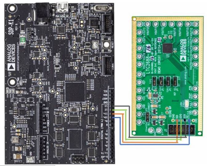
The connections to be made between the SDP-K1 and the DC2873A-B/DC2904A-B are as follows:
SDP-K1 Arduino Header |
DC2873A-B/DC2904A-B Through-Hole |
SCLK/D13 |
SCK |
MISO/D12 |
SDO |
MOSI/D11 |
SDI |
CS/D10 |
CS |
GND |
GND |
Power Supply
The power to the evaluation board should be supplied through the on-board turret connections within the following supply range:
Pin |
Turret |
Voltage Supply |
VCC |
E31 |
5V |
IOVCC |
E10 |
3.3V |
V1+ |
E1 |
5V - 21V |
V2+ |
E14 |
5V - 21V |
V- |
E3 |
-21V - 0 |
GND |
E2 |
GND |
Note
V2+ must be less than or equal to V1+. The VIO_ADJUST jumper on the SDP-K1 board should be on 3.3V position. Remove the jumpers from JP1, JP2, JP3, JP4 for using the board with VIO = 3.3V
Build Guide
Build Prerequisites
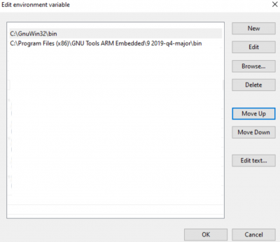
Prior to building a firmware project, it is required to set up an environment so that the build process may find the necessary tools (compiler, linker, SDK etc.). Use the following steps to prepare your environment for building firmware projects for respective platform.
Clone Precision Converters Firmware repository with the –recursive flag:
git clone --recursive https://github.com/analogdevicesinc/precision-converters-firmware
If however you’ve already cloned the repository without the –recursive flag, you may initialize all the submodules in an existing cloned repo with:
git submodule update --recursive --init
Install STM32CubeIDE
Install STM32CubeMX
Building a project
Once the build enviornment is setup, follow the guide below to build your project and generate executable file (.bin/.hex)
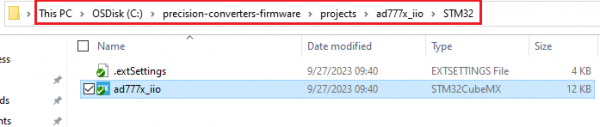
Open the respective project directory by navigating into the “precision_converters_firmware/projects/” folder.
In the “STM32” folder present within the project directory, double click and open the .ioc file present within.
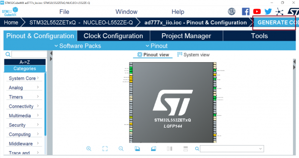
Click on the “Generate Code” option seen on the top right corner
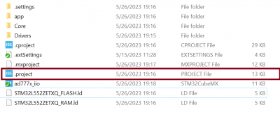
Upon successful generation of drivers for the selected MCU, the autogenerated files would be seen in the same directory where the .ioc file was present. Double click and open the “.project” file seen in the list of files
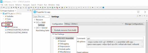
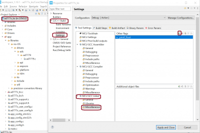
After the project is loaded to the STM32CubeIDE, unfold the adxxxx_iio project seen in the project explorer, right click the “app” folder, select “Settings” under the “C/C++ Build” section on the left pane and un-check the “Exclude resources from build” checkbox. This would ensure that the project specific files are included by the build system
Add compiler flags “-u _printf_float” to the project settings.
Exclude the generated file syscalls.c from the build process

- To generate the binary file, right click on the adxxxx_iio project seen in the project explorer and select “Properties”, select “Settings” under the “C/C++ Build” section on the left pane, select “MCU Post build outputs” under “Tool Settings” section and check the “Convert to binary file (-O binary)” checkbox.

Build the project by right-clicking on the adxxxx_iio project seen in the project explorer and select “Build Project”

Running a project
Once the firmware build is successful and binary file is generated, copy the generated binary into USB drive hosted by your MCU board (e.g. USB drive hosted by MCU board on windows). This will flash the binary file into MCU present on the controller board. Programming might vary based on the tools used for building a project. The ‘Project Build’ section above talks about this exception at the end of all build steps.
Quick Start
If you have some familiarity with the STM32 platform, the following is a basic list of steps required to start running the code, see below for more detail:
Connect the evaluation-board to SDP-K1 board using the Arduino connector and jumper wires.
Connect all the power supplies to the evaluation board as instructed in the hardware connection section.
Connect the controller board to your computer over USB. (Make sure that the VIO_ADJUST is set to 3.3 volts)
Follow the steps mentioned in the Build Guide section above.
- Start up a serial terminal emulator (e.g. Tera Term)
Find the com-port your controller board is connected on and select it.
Set the baud-rate for 230400 - other defaults should be fine.
Reset the controller board and connect.
Use the menu provided over the terminal window to access the evaluation board.
Using the Firmware
The firmware is delivered as a basic, text-based user-interface that operates through a UART on the controller board using the same USB cable that is used to flash the firmware to the boards. Any terminal-emulator should work, but it is not possible for Analog Devices to test everyone. It is necessary to connect a serial terminal-emulator to interact with the running firmware.
Here TeraTerm is used as an example, Analog Devices does not endorse any particular program for this, but TeraTerm works well and is made freely available, other terminals such as CoolTerm, or PuTTY will work.
Configure your serial terminal (Tera Term) for below settings:
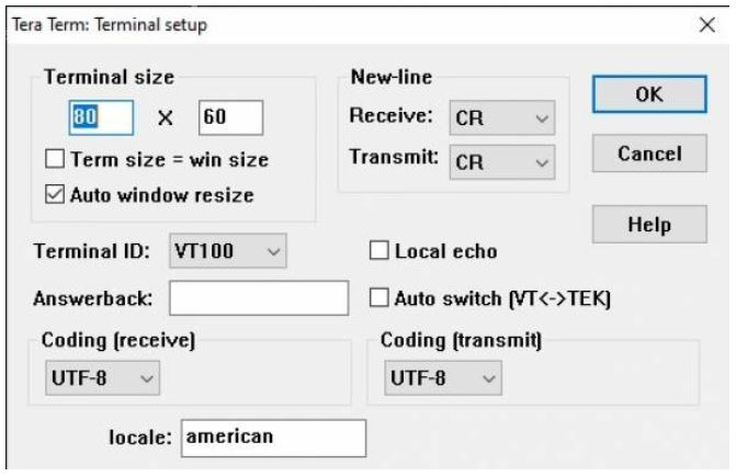
Set the baud-rate for 230400, configure the console terminal settings as shown in the picture above and select the connected controller board’s COM port. If using TeraTerm, you should be able to keep the defaults, however adjustments may need to be made to how carriage return (CR) is handled in order for everything to display correctly.
The LTC268x console main menu looks like below (with Tera Term):
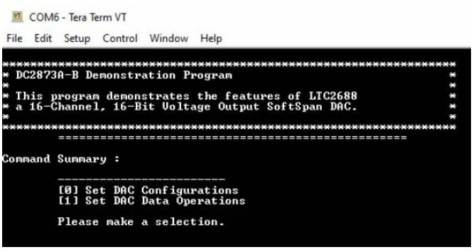
The software is designed to be straight forward to use and requires little explanation. The main menu provides two options:
DAC Configuration: This option lets to configure various DAC parameters such as active channel, span and toggle/dither selection.
DAC Data Operation: This option lets you set the output voltage for DAC channels.
It is hoped that the most features of the LTC2686/8 are coded, but it’s likely that some special functionality is not implemented.
Support
Feel free to ask questions in the EngineerZone