AD590 Console Application
Supported Hardware
Supported Devices:
Supported Evaluation Boards:
Supported Carrier Boards:
Introduction
The page provides a starting point for developing your own code for Analog Devices EVAL-AD590-ARDZ board in your own environment.
This guide will focus on the Analog Devices SDP-K1 controller board, as it is directly compatible with the EVAL-AD590-ARDZ evaluation board and is an STM32 board. Customers are of course, not limited to using the SDP-K1 board for code development, given that any ARM-based, or an STM32 board that satisfies a small set of requirements can use the provided code and it will work with only minor changes to the source (see below).
It is further assumed that SDP-K1 board will be connected to the appropriate AD590 Eval-board such as the EVAL-AD590-ARDZ Evaluation board which has the LTC2488 (SPI) built in with the ability to connect external sensor via headers on the board. It supports STM32 platform
Useful Links
Note
Linux and HDL are not used in emebdded IIO firmware projects but they may be of interest if you require Linux and/or FPGA support.
Hardware Setup
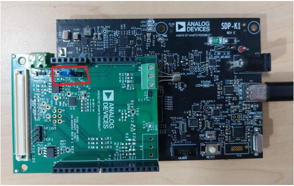
Connecting the EVAL-AD590-ARDZ evaluation board using the SDP connector on the K1 is the simplest and most convenient way to get up and running quickly, simply mate the two boards to together.
The EVAL-AD590-ARDZ board supports remote AD590 through the P6 3-position wire to Board terminal block located at the top left of the eval board. There is no need to adjust the source code to start using the remote sensors. Selecting these devices can be done within the provided application which is described below.
Note
If using the Arduino header pins, compile the software only after uncommenting the #define SDP-120 in ltc2488_user_config.h
The P8 Jumper position can be switched between ARD_5V and SDP_5V according to the connector in use
EVAL-AD590-ARDZ Software
At this time Analog Devices supports code development only on the Mbed online-compiler. See here for instructions on setting up an account and using the compiler. Analog Devices may, at a later date support other offline-IDE’s. This guide focuses on the SDP-K1, connected to the EVAL-AD590-ARDZ board, but it should be general enough to cover any compatible controller board (the controller board should be an STM32 board, and expose at least SPI or I2C and some GPIO’s).
The software described below allows for an STM32 board to be connected with an Analog Devices evaluation board. Unmodified, the code will communicate over any serial terminal emulator (CoolTerm, putty, etc) using the UART provided by the controller board over USB.
The software provides a basic user-interface for interacting with temperature sensors on the evaluation-board. All the main functionality of the AD590 is provided in the application-code in abstracted form and the user is free to customize the software to suit their own needs for working with the sensors
Build Guide
Build Prerequisites
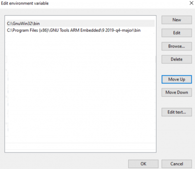
Prior to building a firmware project, it is required to set up an environment so that the build process may find the necessary tools (compiler, linker, SDK etc.). Use the following steps to prepare your environment for building firmware projects for respective platform.
Clone Precision Converters Firmware repository with the –recursive flag:
git clone --recursive https://github.com/analogdevicesinc/precision-converters-firmware
If however you’ve already cloned the repository without the –recursive flag, you may initialize all the submodules in an existing cloned repo with:
git submodule update --recursive --init
Install STM32CubeIDE
Install STM32CubeMX
Building a project
Once the build enviornment is setup, follow the guide below to build your project and generate executable file (.bin/.hex)
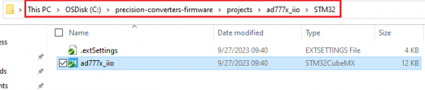
Open the respective project directory by navigating into the “precision_converters_firmware/projects/” folder.
In the “STM32” folder present within the project directory, double click and open the .ioc file present within.
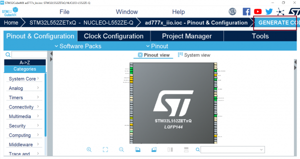
Click on the “Generate Code” option seen on the top right corner
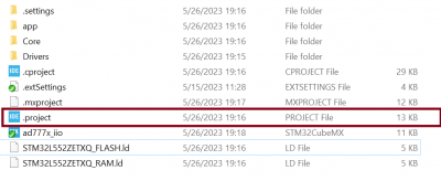
Upon successful generation of drivers for the selected MCU, the autogenerated files would be seen in the same directory where the .ioc file was present. Double click and open the “.project” file seen in the list of files
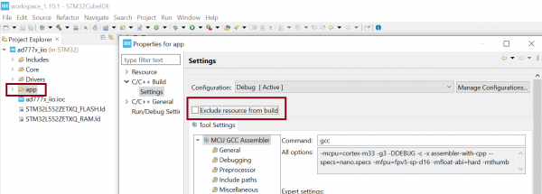
After the project is loaded to the STM32CubeIDE, unfold the adxxxx_iio project seen in the project explorer, right click the “app” folder, select “Settings” under the “C/C++ Build” section on the left pane and un-check the “Exclude resources from build” checkbox. This would ensure that the project specific files are included by the build system
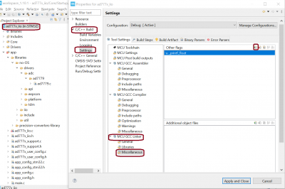
Add compiler flags “-u _printf_float” to the project settings.
Exclude the generated file syscalls.c from the build process

- To generate the binary file, right click on the adxxxx_iio project seen in the project explorer and select “Properties”, select “Settings” under the “C/C++ Build” section on the left pane, select “MCU Post build outputs” under “Tool Settings” section and check the “Convert to binary file (-O binary)” checkbox.

Build the project by right-clicking on the adxxxx_iio project seen in the project explorer and select “Build Project”

Running a project
Once the firmware build is successful and binary file is generated, copy the generated binary into USB drive hosted by your MCU board (e.g. USB drive hosted by MCU board on windows). This will flash the binary file into MCU present on the controller board. Programming might vary based on the tools used for building a project. The ‘Project Build’ section above talks about this exception at the end of all build steps.
Quick Start
If you have some familiarity with the STM32 platform, the following is a basic list of steps required to start running the code, see below for more detail.
Connect the evaluation-board to the STM32 board using the SDP-120 or Arduino connector. (Switch the P8 Jumper accordingly).
Connect the controller board to your computer over USB. (Make sure that the VIO_ADJUST is set to 3.3 volts)
Go to the link provided above in the ‘Build Guide’ section and import code into Keil Studio Web IDE.
Ensure SDP-K1 controller board is selected (top right of online-compiler page).
Edit ltc2488_user_config.h to (defaults to SDP connector) enable the SDP-120 Header, if not using the Arduino connector. Do this by uncommenting #define SDP-120 in ltc2488_user_config.h Switch the power jumper accordingly on the P8 power select jumper
Compile the code.
After a successful compile, a binary will be downloaded to your computer - store this somewhere.
Drag and drop this binary to the USB drive hosted by your controller board.
- Start up a terminal emulator,
Find the com-port your controller board is connected on and select it.
Set the baud-rate for 230400 - other defaults should be fine.
Reset the controller board and connect.
Use the menu provided over the terminal window to access the evaluation board.
Using the Firmware
The firmware is delivered as a basic, text-based user-interface that operates through a UART on the controller board using the same USB cable that is used to flash the firmware to the boards. Any terminal-emulator should work, but it is not possible for Analog Devices to test everyone. It is necessary to connect a serial terminal-emulator to interact with the running firmware.
Here TeraTerm is used as an example, Analog Devices does not endorse any particular program for this, but TeraTerm works well and is made freely available, other terminals such as CoolTerm, or PuTTY will work.
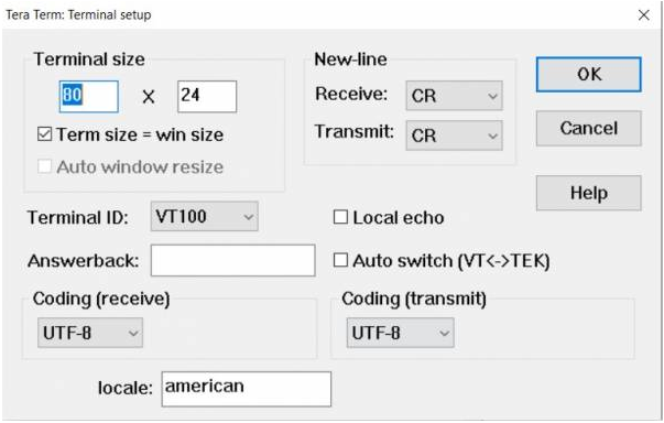
Set the baud-rate for 230400, configure the console terminal settings as shown in the picture above and select the connected controller board’s COM port. If using TeraTerm, you should be able to keep the defaults, however adjustments may need to be made to how carriage return (CR) is handled in order for everything to display correctly.
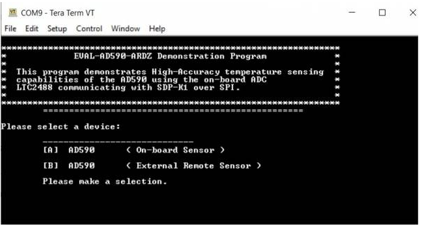
The software is designed to be straight forward to use and requires little explanation. Simply select which sensor you would like to use, whether you want to use the internal sensor or a remote one and then simply enter a number corresponding to the required command and follow the on-screen prompts. The code is also written with a view to keeping things simple, you do not have to be a coding-ninja to understand and expand upon the delivered functions.
It is hoped that the most features of the AD590 are coded, but it’s likely that some special functionality is not implemented.
Support
Feel free to ask questions in the EngineerZone