AD3530R IIO Application
Supported Hardware
Supported Devices:
Supported Evaluation Boards:
Supported Carrier Boards:
Introduction
This page gives an overview of using the ARM platforms supported firmware example with Analog Devices AD353xr Evaluation board and SDP-K1 controller board. This example code leverages the ADI developed IIO (Industrial Input Output) ecosystem to evaluate the AD353xr device by providing a device debug and data capture support.
The interface used for communicating with PC based IIO clients is either Virtual Serial Or UART. IIO Firmware leverages the ADI created no-os and platform driver software layers to communicates with IIO device.
Note
This code has been developed and tested on the SDP-K1 Controller Board with Arduino headers. However, the same code can be used with minimal modifications on any STM32 board which has Arduino Header support on it.
Useful Links
Note
Linux and HDL are not used in emebdded IIO firmware projects but they may be of interest if you require Linux and/or FPGA support.
Hardware Connections
Required: SDP-K1, EVAL-AD353XRARDZ board and USB cable.
Connect the EVAL-AD353XRARDZ board to SDP-K1 board (or any STM32 controller board). Connect controller board to the PC using the USB cable.

Jumper Settings
SDP-K1:
Connect the VIO_ADJUST jumper on the SDP-K1 board to 3.3V position to drive SDP-K1 GPIOs at 3.3V
EVAL-AD353XR:
Please refer to the respective board user guide on the product page of the chosen device.
SDP-K1 is powered through USB connection from the computer. SDP-K1 MCU board acts as a serial device when connected to PC, which creates a serial ports to connect to IIO client application running on PC. The serial port assigned to a device can be seen through the device manager for windows-based OS as shown below:
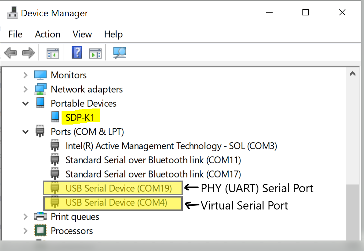
Note
The serial port naming is used differently on different operating systems. For example, Linux uses terms such as dev/ttyUSB* and Mac uses terms such as dev/tty.USB*. Please check serial port naming for your selected OS.
Build Guide
Build Prerequisites
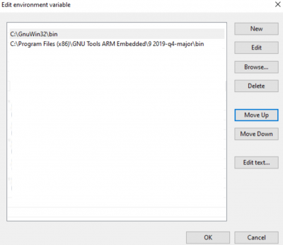
Prior to building a firmware project, it is required to set up an environment so that the build process may find the necessary tools (compiler, linker, SDK etc.). Use the following steps to prepare your environment for building firmware projects for respective platform.
Clone Precision Converters Firmware repository with the –recursive flag:
git clone --recursive https://github.com/analogdevicesinc/precision-converters-firmware
If however you’ve already cloned the repository without the –recursive flag, you may initialize all the submodules in an existing cloned repo with:
git submodule update --recursive --init
Install STM32CubeIDE
Install STM32CubeMX
Building a project
Once the build enviornment is setup, follow the guide below to build your project and generate executable file (.bin/.hex)
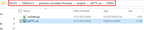
Open the respective project directory by navigating into the “precision_converters_firmware/projects/” folder.
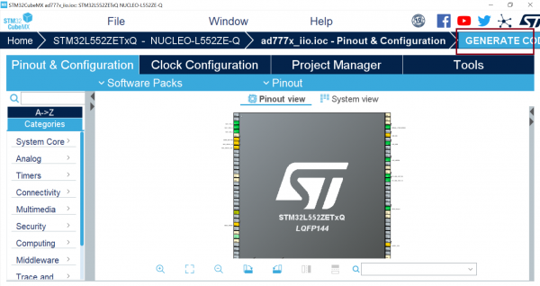
In the “STM32” folder present within the project directory, double click and open the .ioc file present within.
Click on the “Generate Code” option seen on the top right corner
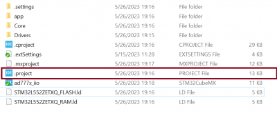
Upon successful generation of drivers for the selected MCU, the autogenerated files would be seen in the same directory where the .ioc file was present. Double click and open the “.project” file seen in the list of files
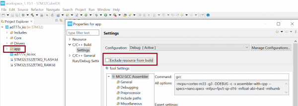
After the project is loaded to the STM32CubeIDE, unfold the adxxxx_iio project seen in the project explorer, right click the “app” folder, select “Settings” under the “C/C++ Build” section on the left pane and un-check the “Exclude resources from build” checkbox. This would ensure that the project specific files are included by the build system
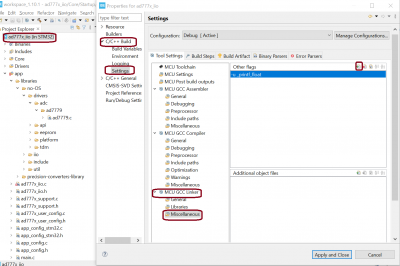
Add compiler flags “-u _printf_float” to the project settings.
Exclude the generated file syscalls.c from the build process

- To generate the binary file, right click on the adxxxx_iio project seen in the project explorer and select “Properties”, select “Settings” under the “C/C++ Build” section on the left pane, select “MCU Post build outputs” under “Tool Settings” section and check the “Convert to binary file (-O binary)” checkbox.

Build the project by right-clicking on the adxxxx_iio project seen in the project explorer and select “Build Project”

Running a project
Once the firmware build is successful and binary file is generated, copy the generated binary into USB drive hosted by your MCU board (e.g. USB drive hosted by MCU board on windows). This will flash the binary file into MCU present on the controller board. Programming might vary based on the tools used for building a project. The ‘Project Build’ section above talks about this exception at the end of all build steps.
Using the IIO Ecosystem
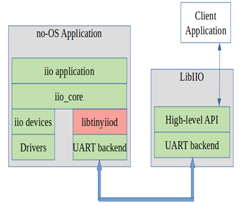
IIO (Industrial Input/Output) is a flexible ecosystem that allows various client tools to communicate with IIO device to configure the device, capture device data, generate waveforms, access registers, etc. Below diagram demonstrates the high level architecture of IIO ecosystem.
https://wiki.analog.com/resources/tools-software/linux-software/libiio
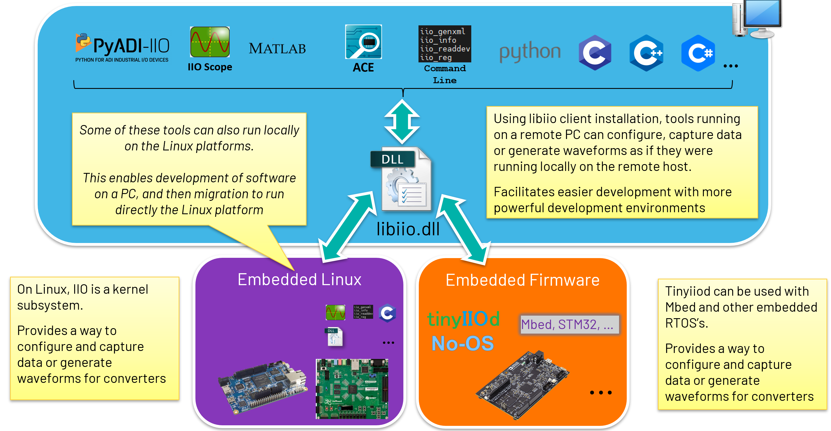
IIO Tools:
IIO Oscilloscope ADI IIO Oscilloscope is a cross platform GUI application, which demonstrates how to interface different evaluation boards within an IIO ecosystem. It supports raw data capture, FFT analysis, DMM measurement, device configuration, register read/write and data streaming.
pyadi-iio: Python interfaces Analog Devices python interfaces for hardware with Industrial I/O drivers. It provides python based scripts for raw data capture, device configuration and register read/write.
ACE ADI’s “Analysis, Control, Evaluation” (ACE) is a desktop software application which allows the evaluation and control of multiple evaluation systems.
Precision Converters MATLAB Toolbox Toolbox created by ADI to be used with MATLAB and Simulink with ADI Precision products.
IIO Command Line Command line interface for accessing IIO device parameters.
Pocketlab ADI Pocketlab is a display based GUI client. It supports raw data capture, FFT analysis, DMM measurement, device configuration, register read/write.
Note
These are the general evaluation and prototyping tools for Precision Converters but not all converters are supported. In some cases these tools provide generic IIO support (e.g. ACE, IIO Oscilloscope) and can provide basic functionality with any IIO based system. In other cases if a part is not currently supported, it is possible to add support for converters that you need due to the open source nature of the tools.
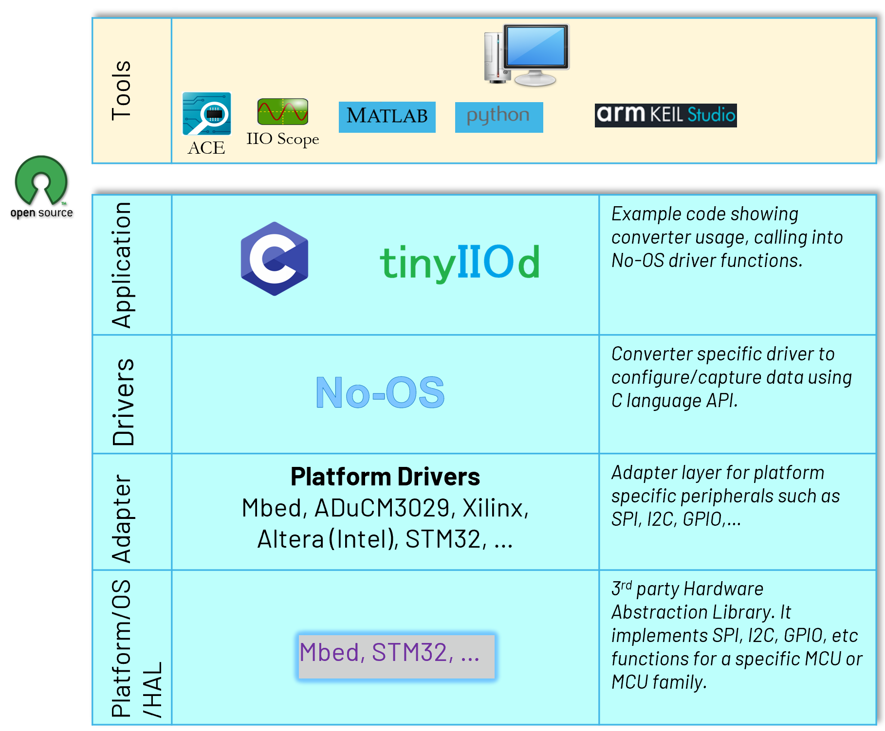
IIO Firmware Structure
Below diagram illustrates the architecture of Precision Converters IIO firmware applications.
Waveform Generation
The Firmware supports two modes of data streaming using the SPI-DMA technique for Waveform generation from the IIO client
Configuring data streaming modes
The IIO client can configure the data streaming mode by setting the “data_streaming_mode” iio attribute. The supported modes are:
Single Instruction mode
Streaming mode
Please refer to the data sheet for more details on the data streaming modes.
Configuring Sampling Frequency
Using the “sampling_frequency” iio attribute, the rate at which the converter updates the data can be controlled. In this case, it can go all the way from 1000SPS to 570KSPS in case of Single Instruction mode of data streaming. In case of Streaming mode, the sampling frequency is fixed at 1.4MSPS and non-configurable. The attribute is set to maximum sampling rate supported by default by the platform and can be varied in the accepted ranges by writing to the it.
Based on the sampling_frequency input, the FW calculates the nearest possible period value (based on the prescalers, counter resolutions and other settings) that can be acheived on the counter and returns back the same after setting it to the counter registers.
- Here’s a simple formula that calculates the same:

When to use what mode?
Any combination of channels can be sequenced in case of Single Instruction Mode and sampling_frequency (update rate) can be varied as per the requirement. However, since every transaction is a single instruction (requires an address plus data phase), the maximum achievable sampling rate is limited to 570KSPS.
On the other hand, in case of Streaming mode, only serial channels are allowed to be sequenced (as the chip assumes the regiters to be contiguous in streaming mode) and the sampling frequency is fixed at 1.4MSPS (the highest throughput possible at a given SPI clok frequency). This mode is useful when the maximum sampling rate is required and the data is to be streamed continuously.
Support
Feel free to ask questions in the EngineerZone