IIO Oscilloscope
Installation
Refer this page to install IIO oscilloscope for Windows or Linux OS: IIO Oscilloscope (Client)
Running on Linux
Refer this page: https://wiki.analog.com/resources/tools-software/linux-software/iio_oscilloscope
Running on Windows
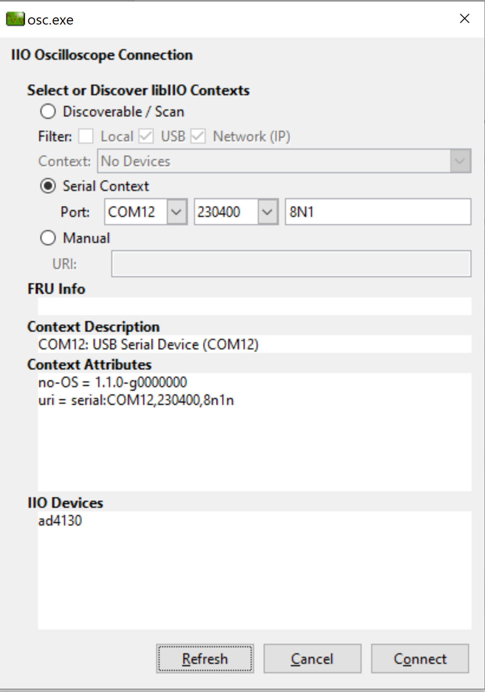
Open the IIO Oscilloscope application from start menu and configure the serial (UART) settings as shown below. Click on refresh button and device should pop-up in the IIO devices list.
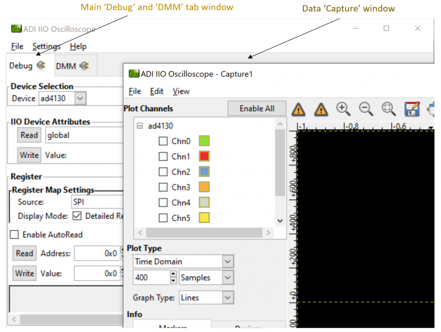
Click ‘Connect’ and it should by default open the data ‘Capture’ window. You can drag aside or close this window to see the main ‘Debug and DMM’ tab window.
Configure/Access Device Attributes (Parameters)
The IIO Oscilloscope allows user to access and configure different device parameters, called as ‘Attributes“. There are 3 types of attributes:
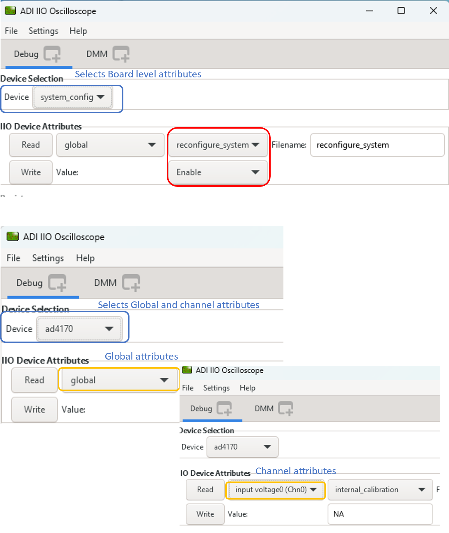
Device Attributes (Global): Access/Configure common device parameters.
Channel Attributes (Specific to channels): Access/Configure channel specific device parameters.
Board Level Attributes (Can be Global and Channel specific): Configure the board level parameters. Projects only receive the board-level attribute when deemed necessary, thus it is not a standard inclusion
Note
After any board-level attribute is configured, the ‘reconfigure_system’ attribute must be enabled. This step ensures that the IIO Device is reinitialized and the changes made through the selected board-level attributes are applied. If this step is neglected, the changes made on the attributes will not take effect on the device. The IIO Oscilloscope application must be closed and re-opened to ensure continued communication with the IIO Device.
Using IIO Oscilloscope for ADCs
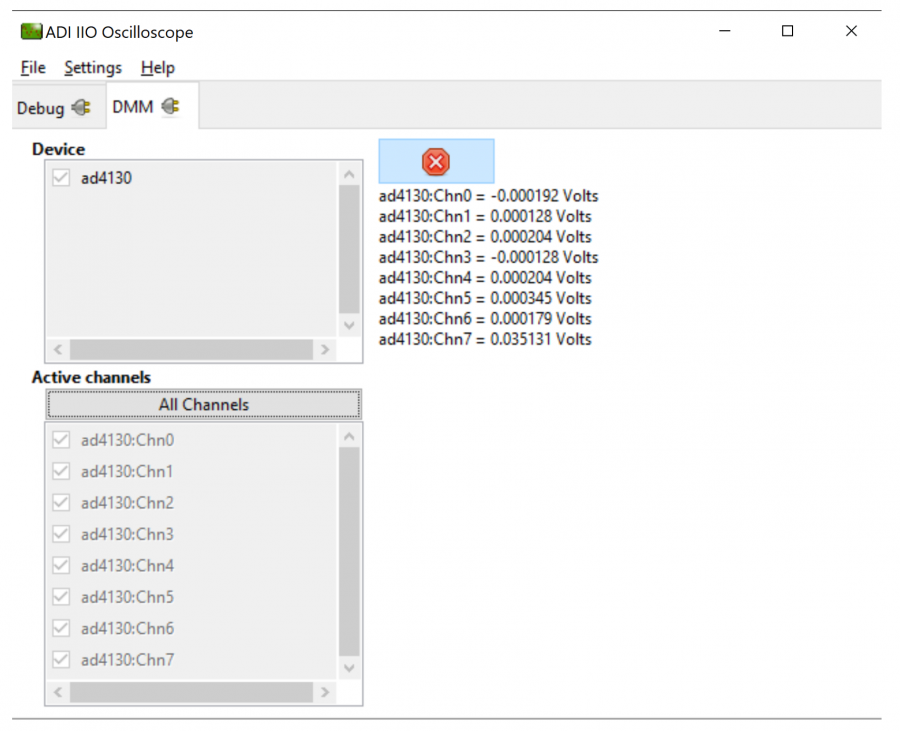
Using DMM Tab to Read DC Voltage on Input Channels
DMM tab can be used read the instantaneous voltage applied on analog input channels. Simply select the device and channels to read and press start button.
Note
The voltage is just instantaneous, so it is not possible to get RMS AC voltage or averaged DC voltage. Also, when using DMM tab, do not access/use the Data capture or Debug tab as this could impact data capturing. All uses same communication bus to access the data which could result into access/busy conflicts during data capture.
IIO Data Capture for ADCs
Introduction
This page focuses on the IIO firmware part of ‘Data Capturing. The “AD7606 IIO Application” is used as a reference for this discussion.
IIO clients can be used to capture and visualize the continuous analog or discrete signals from any ADC device using a IIO firmware application developed for that particular device. This allows user to monitor a real-time data. Using this firmware, a user can perform device calibration, change the gain, voltage range, data rate, etc. (based on device used) and observe the effects that different configurations have on the data displayed on IIO client. IIO clients also allows users to save the data, which can further be used to process and analyze it.
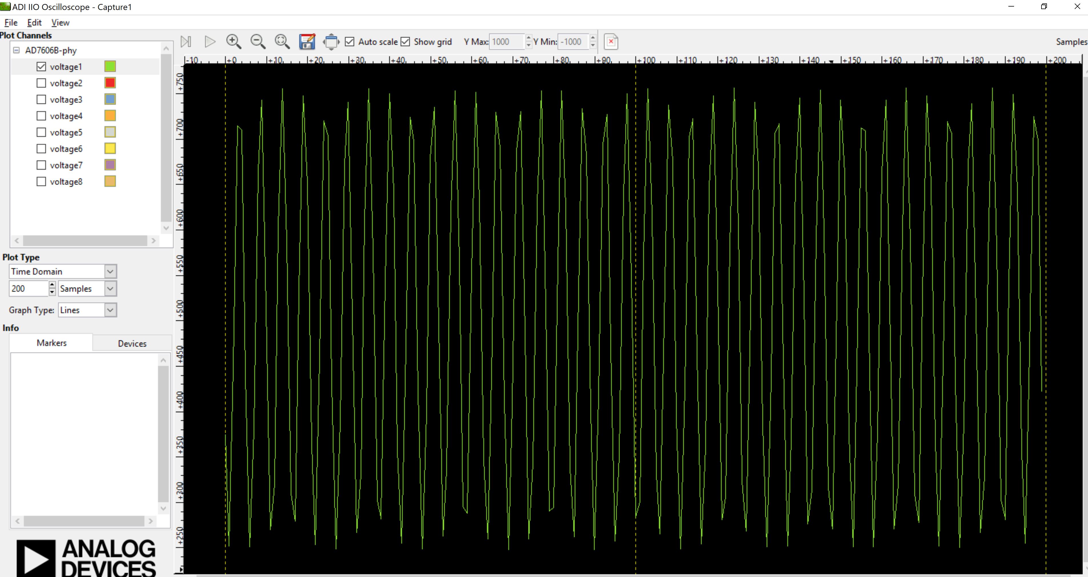
The diagram below shows the continuous capture of signals on an AD7606 ADC, which is an 8-channel DAS. A 1Khz signal is applied on inputs of all 8 analog channels. The max data capturing rate in firmware is ~30 to 40 KSPS. The data is transmitted from firmware application using Virtual Serial or UART serial link.
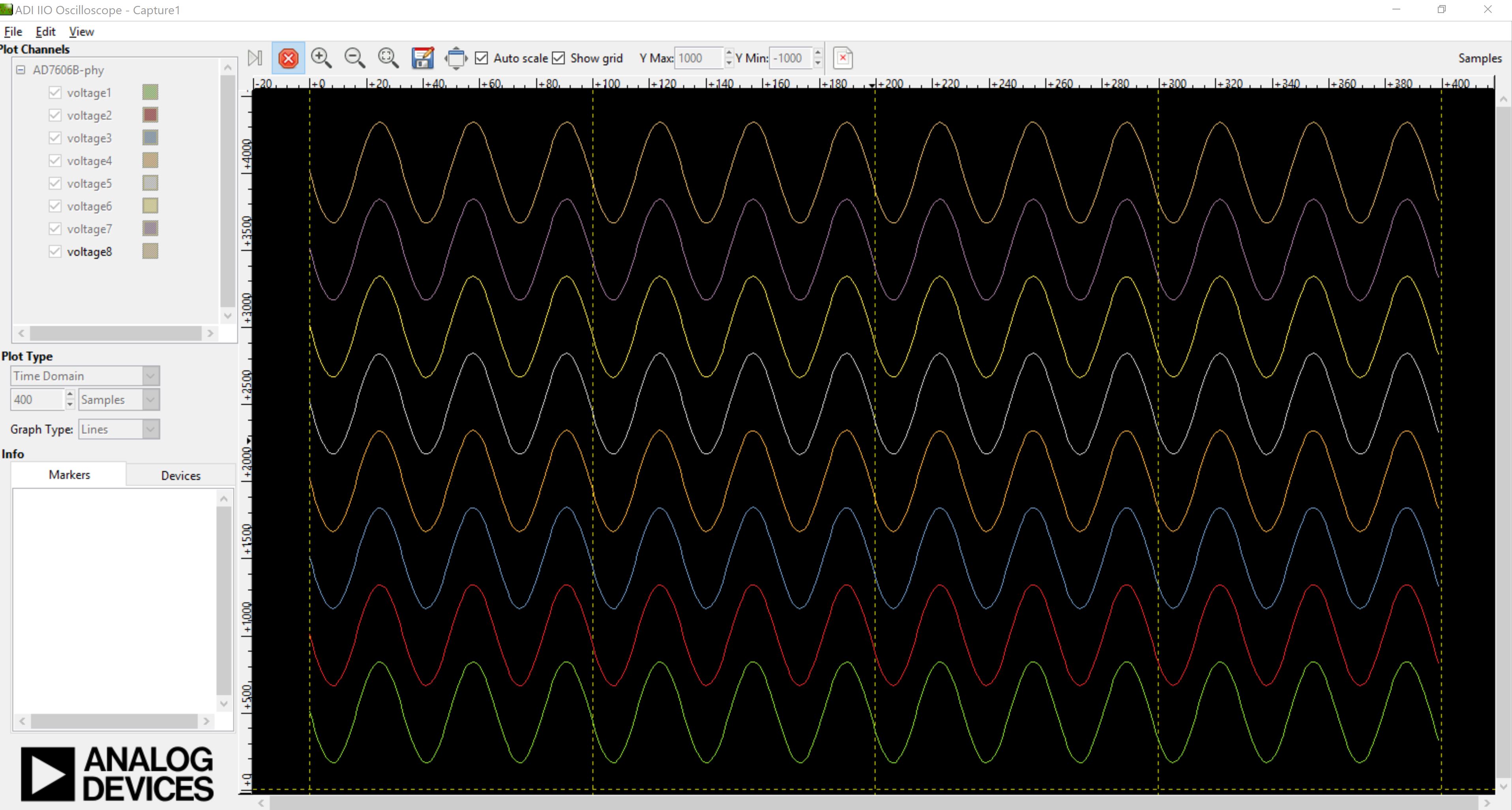
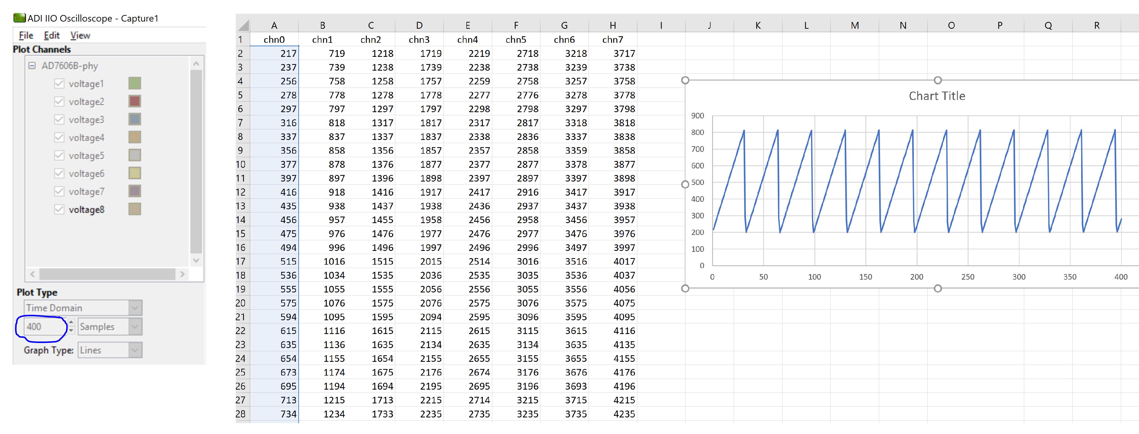
The channels for which data is to be captured can be selected from the GUI window, along with the number of samples to display on screen in a single data read query. As shown below, all 8 channels are selected for data capture and the number of requested samples is set at 400 (default). This means, IIO oscilloscope requests 400 samples per channel, so in this case total 3200 samples. The channels are stored as shown below:
Data Capture from IIO Device
To capture the data from IIO device, simply select the device and channels to read/capture data. The data is plotted as “ADC Raw Value” Vs “Number of Samples” and is just used for Visualization. The data is read as is from device without any processing. If user wants to process the data, it must be done externally by capturing data from the Serial link on controller board.
Note
The DMM or Debug tab should not be accessed when capturing data as this would impact data capturing. All uses same communication bus to access the data which could result into access/busy conflicts during data capture.
Time Domain plot:
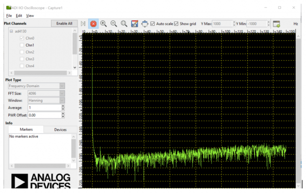
Frequency Domain plot:
Note
Select number of samples and channels according to sampling rate of your device. For very slow ODRs, the data capturing would be too slow and IIO oscilloscope might become unresponsive waiting for data to be received from IIO device.
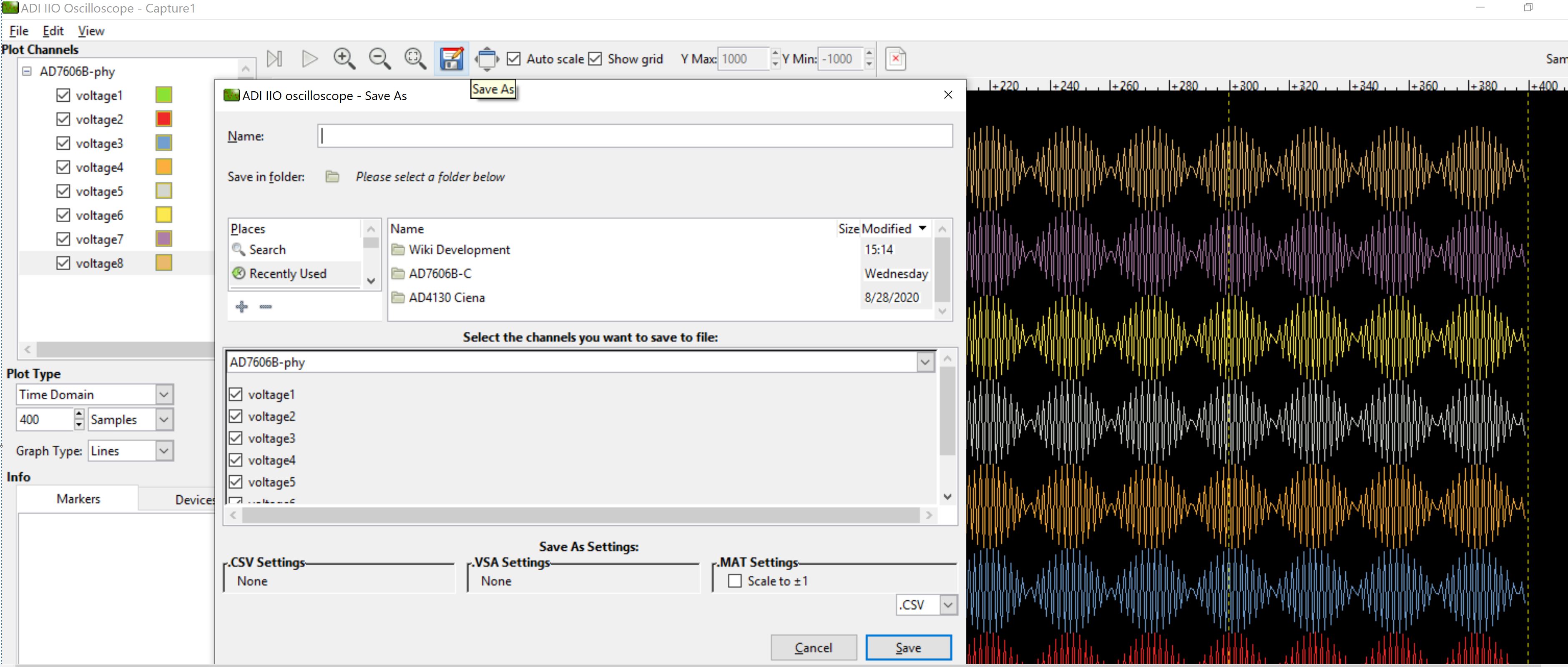
Saving Captured Data
The data on IIO oscilloscope can be saved for further processing and analysis. The data is saved using a .csv format. The data can be captured for each selected channel during save option and only requested number of samples can be saved. So if 400 samples are requested, the data for only 400 samples would get saved into .csv file. The data is raw adc data and no extra processing is performed it while saving or capturing.
The data saving feature is also available with other IIO client applications such as python and ACE.
Limitations of Data Capture Using IIO Application
There are 3 major factors which can potentially impact the data capturing:
Sampling/Capturing Rate of ADC
Data Transmission Rate (serial link) of MCU
Buffer size limitations in the firmware (MCU RAM size)
ADC Data Sampling/Capturing Rate:
The data capturing or sampling rate defines the maximum rate/speed at which data can be sampled and captured from the ADC using the IIO firmware application. For ADC’s, typical time to capture single ADC sample is defined as:
Time to capture single sample: ADC acquisition time + ADC sampling time + ADC data read time over digital interface
For AD7606, this time is typically 28usec for all 8-channels (obtained in IIO firmware). AD7606 captures all 8-channels in single conversion cycle. When calculating the sample rate per second, it is obtained as ~284 KSPS for all 8 channels (28usec / 8 = 3.5usec. Sample rate/second = 1/3.5usec = 284 KSPS). This gives sample rate per channel as ~35KSPS.
Data capturing rate is also limited because of an additional overhead in the MCU firmware such as interrupt context switching time, SPI (digital interface) clock frequency, MCU clock speed, etc.
35Khz therefore can be considered as the sampling frequency. As per ‘Nyquist–Shannon sampling theorem’, the sampling frequency should theoretically be greater than twice the analog input frequency for faithful reproduction of the signal after conversion. However, in practice sampling frequency should be high enough to capture multiple slices/samples in given period, so that the input signal is replicated smoothly.
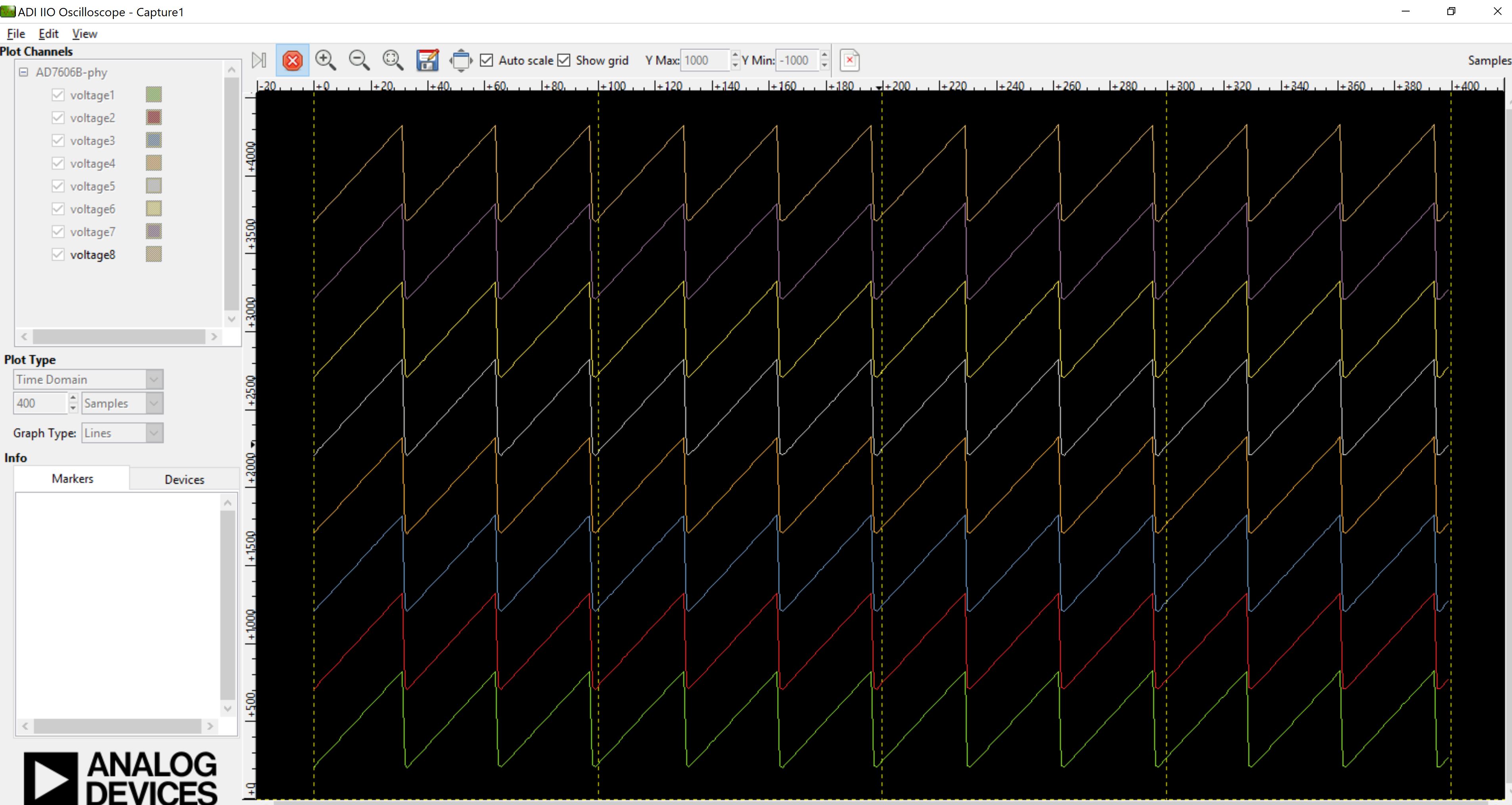
Due to this limitations, IIO firmware can sample input frequencies which are very less than max possible data rate. In case of AD7606, it is possible to sample the signals with frequencies of 4Khz and less when no oversampling is present. At OSR > 0, the data rate drops down and so higher frequency signals can’t be reproduced correctly. Below plot is captured with 17Khz analog input on channel 1 and it can be seen that the signal is not a pure sine wave.
Data Transmission Rate (serial link) of MCU:
This is the rate or speed at which data can be transmitted to IIO client over the serial link (e.g. UART or Virtual serial). The data transmission link must be fast enough the transmit the buffered data from firmware for continuous capture. The IIO clients requests data in aperiodic manner, meaning that new data capture request is sent immediately when data from previous request is received.
Capturing Rate < Transmission Rate:
If data capturing rate is lower than transmission rate, the IIO client can wait for certain period of time before sufficient samples are captured in the buffer. If time to capture these samples is higher than IIO client timeout period, the IIO client aborts the request and attempt new capture request. Therefore user must always ensure that the timeout factor of IIO clients is large enough to handle slower sampling rates (ODRs) of ADCs.
Main factor that determines the IIO oscilloscope timeout is ‘sampling_frequency’ attribute. If this attribute is not defined, the timeout period for IIO oscilloscope during data capture is set to 2sec default, however, if this attribute is defined, the time is calculated as: number of requested samples * (1 / sampling_frequency). For example, if sampling frequency is set as 400SPS, the timeout period is:
timeout = 400 (requested samples) * (1 / 10000 SPS) + 1sec = 1.4 sec
There is a fix employed for the above in the latest version of iio-oscilloscope Please follow the below steps to increase the timeout of iio oscilloscope: * Download the iio-oscilloscope.exe * Navigate to the configuration file .osc_profile.ini (This can be usually found at: C:UsersdishaAppDataLocal) * Add a variable capture_timeout and set it to a value (in ms) suited for your application.
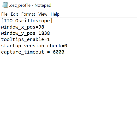
An example of a minimum content of a .ini file: [IIO Oscilloscope] capture_timeout=5000
Capturing Rate > Transmission Rate:
If data capturing rate is too high compared to the transmission rate, the data acquisition into a buffer happens faster. So data buffer might fill faster compared to emptying operation. This might lead to a discontinuity on data visualization on IIO oscilloscope side as data visualization is limited by data transmission rate in this case (with slower serial communication link). If communication link is faster and matches to capturing/sampling rate, the visualization of data would be more continuous. Having a large data buffer in the firmware can minimize this issue to large extend but it can’t completely solve the problem.
Buffer size limitations in the firmware:
Size of data buffer on the firmware is always restricted due to MCU memory size. The requested number of samples from IIO client application therefore must always be less than the total size of data buffer. If requested samples are more than the size of data buffer, IIO firmware returns negative error code to IIO client which then terminates the data capture request.
Buffer size can be increased to larger value by making use of interna/external RAMs. For example, SDP-K1 MCU board has 16Mbytes of onboard SDRAM, which allows larger data buffer size in the firmware. By enabling SDRAM in the SDP-K1 targetted Mbed firmware (app_config.h file), the data buffer size can be increased to 16Mbytes.
The Nucleo-H563 does not have an SDRAM supported. Hence, the data buffer size is limited to the buffer provided in the firmware.
/* Enable/Disable the use of SDRAM for ADC data capture buffer */
//#define USE_SDRAM     // Uncomment to use SDRAM for data buffer
IIO firmware maintains the circular data buffer with dedicated read and write indices. Below diagram illustrates the use of circular buffer in the firmware.

Using IIO Oscilloscope for DACs
IIO Data Streaming for DACs
Introduction
IIO clients can be used to load and stream data to DAC devices using an IIO firmware application developed for that device. Using this firmware, a user can configure various settings on the device and load the data using the DAC Data Manager tab. The data is transmitted using Virtual Serial or UART serial link. The input data to be streamed can be loaded in a binary data file or a MAT file (.mat) format.
The channels for which data is to be streamed can be selected from the GUI window, and the number of samples per channel will be taken from the input data file provided. So, for an 8-channel DAC, if all 8 channels are selected for streaming, the input file should contain 3200 samples, considering 400 samples per channel.
IIO client allows data to be streamed to the iio device in two ways: either cyclic streaming enabled or disabled. When the cyclic buffer streaming is enabled, the buffer repeats itself, and the same data is streamed over and over indefinitely until stopped.
Data Streaming to IIO Device
The DAC Data Manager tab on the IIO Oscilloscope allows streaming data to supported iio devices. The input data file can be a binary file (.bin) or a MAT file (.mat).
Note
DAC Data Manager is not available in versions below 0.15. To use the Data Manager, the IIO Oscilloscope application must be upgraded to the most recent versions.
Creating binary files for data streaming
pyadi-iio: Python interfaces The PyADI module allows users to create binary data files from the input data using the tx class. The CLI (Command Line Interface) script adistream.py allows the user to create various types of waveforms like sine, triangular, pwm, etc and store them to a binary file.
Loading and Streaming the Data
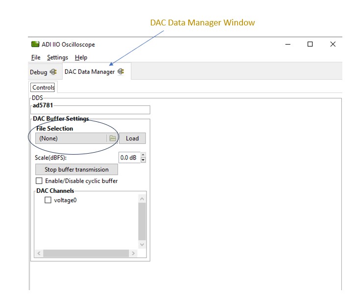
On the IIO Oscilloscope, open the DAC Data Manager tab as indicated below after connecting to the iio device.
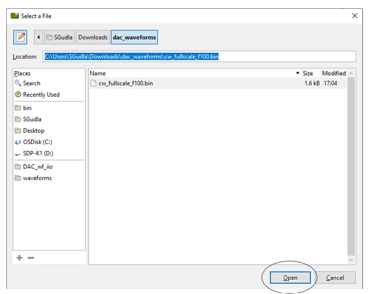
Click on the File Selection section to input the wavefrom data binary file created. Copy the binary file path and paste it in the Location section, then click Open.
Note
The input data file shall contain data according to the number of active channels enabled, and otherwise may result in incorrrect data being streamed.
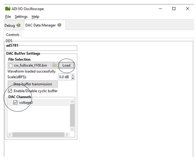
Once the required channels are enabled, use the cyclic buffer checkbox to enable or disable cyclic streaming of data. Click the Load button to load the data. The message “Waveform loaded successfully” shows up if the data is loaded correctly.
Note
The Debug tab should not be accessed when streaming data, as this would impact data streaming. All uses same communication bus to access the data which could result into access/busy conflicts during data streaming.
If Enable/Disable cyclic buffer is unchecked, streaming stops once all the data from the file is loaded, and if the cyclic buffer checkbox is checked, “Stop buffer transmission” button needs to be clicked to end the data streaming.
Limitations of Data Streaming Using IIO Application
DAC Sampling/Update Rate:
The sampling rate or update rate defines the maximum rate/speed at which data can be loaded and updated onto the DAC output using the IIO firmware application. For DACs, typical time to update single sample is defined as:
Time to update single sample: DAC data write time over digital interface + DAC conversion & output response time
Data update rate is also limited because of additional overhead in the MCU firmware, such as interrupt context switching time, SPI (digital interface) clock frequency, MCU clock speed, etc.
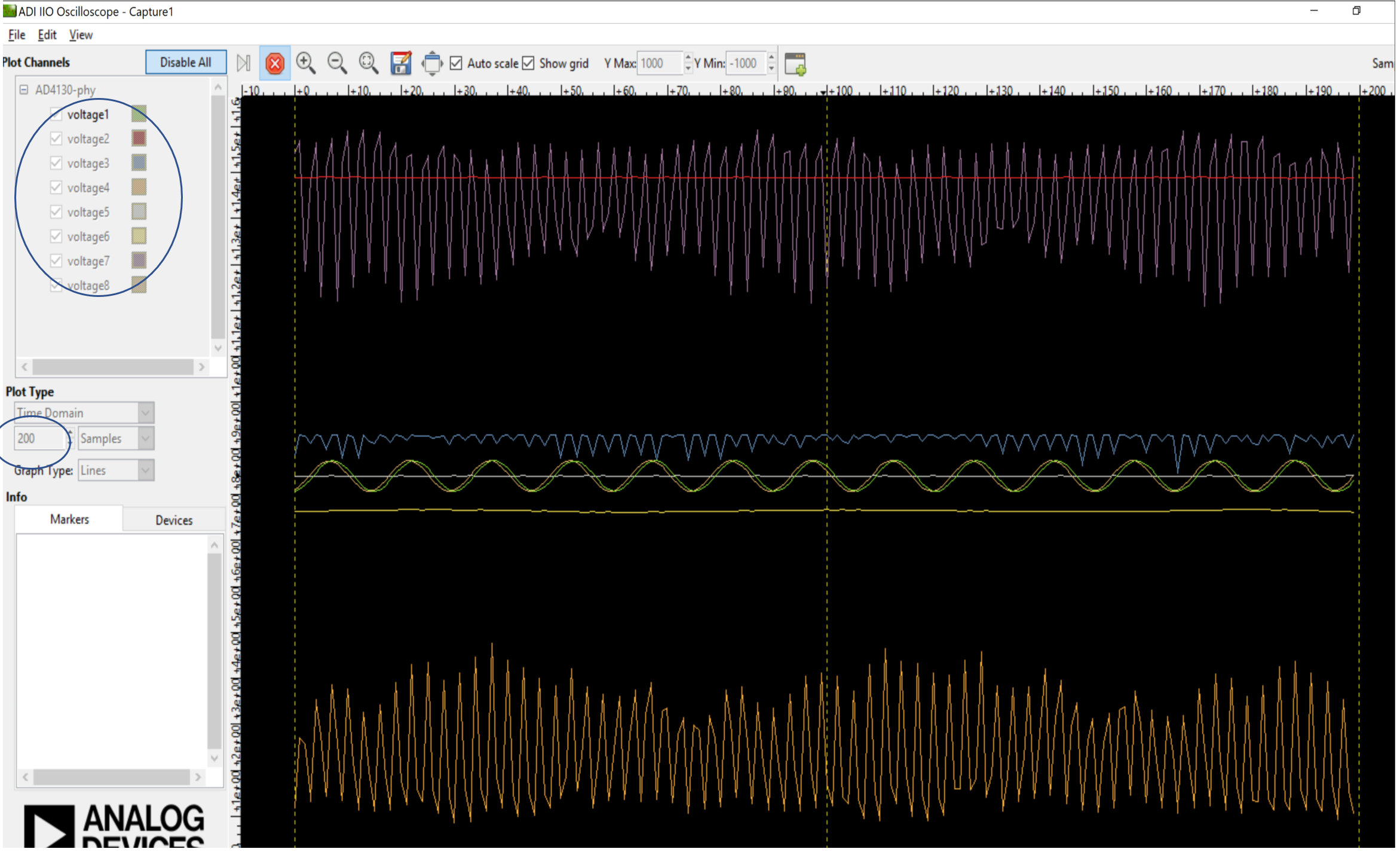
The “AD579X IIO Application” is used as a reference here. For AD5790, which is a one-channel VDAC, the update rate is 71.4 KSPS. So, if a sine wave with 200 data points is to be streamed, the output frequency that can be seen will be 357 Hz (fo = fs/np = Sample rate/number of data points = 71.4K/200). The effective output frequency might also vary based on the number of channels enabled on the device.
Data Transmission Rate (serial link) of MCU:
This is the rate or speed at which data can be transmitted from the IIO client over the serial link (e.g. UART or Virtual serial). This especially needs to be considered when cyclic buffer streaming is disabled and the buffer data needs to be transferred from the client in real-time for a continuous update.
Buffer size limitations in the firmware:
Size of data buffer on the firmware is always restricted due to MCU memory size. The required number of samples to be streamed from the IIO client application therefore must always be less than the total size of data buffer. If the required streaming samples number is more than the size of data buffer, IIO firmware returns negative error code to IIO client which then terminates the data streaming request.
Buffer size can be increased to larger value by making use of internal/external RAMs, if supported by the MCU platform enabled by the project. For example, SDP-K1 MCU board has 16Mbytes of onboard SDRAM, which allows larger data buffer size in the firmware. By enabling SDRAM in the SDP-K1 (using the macro in app_config.h file), the data buffer size can be increased to 16Mbytes.