Steps:
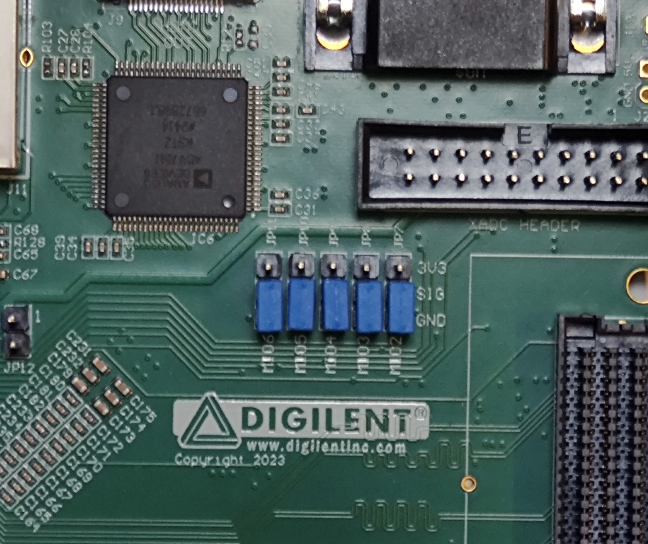
Set the ZedBoard jumpers to no-OS configuration (all of the configuration jumpers to GND).
- Connect the ZedBoard to your desktop with 2 Micro-USB cables.
One for UART (J14)
One for JTAG (J17)
Connect the barrel jack power supply to the ZedBoard.
Make sure the VADJ is set to 2V5.
Make sure the jumpers on the evaluation board are set for your desired configuration. The configuration in this quickstart guide is:
Jumper |
Position |
|---|---|
LK1 |
A |
LK2 |
A |
LK3 |
A |
LK4 |
B |
LK5 |
B |
LK6 |
B |
LK7 |
A |
LK8 |
B |
LK9 |
A |
LK10 |
A |
LK11 |
Set |
LK12 |
Set |
Connect the Evaluation Board to the ZedBoard by using a SDP to FMC interposer on the FMC connector of the ZedBoard (J1).
Connect a 3.3V Voltage Source to the J12 Connector of the Evaluation Board.
Connect an oscilloscope to the MUX_OUT Connector of the Evaluation Board.
Build the boot files and run the project. You can follow this guide
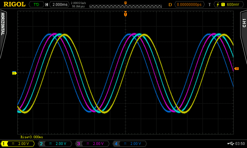
Using the oscilloscope check your output.