Simulink Controller Models
Warning
The AD-FMCMOTCON1-EBZ is a legacy product and is no longer actively supported. This documentation is provided for reference only.
The Vivado HDL design is provided with an integrated FOC and speed & torque controller generated from a Simulink model provided by MathWorks. The controller is designed in Simulink and the corresponding HDL code is generated using the MathWorks HDL Coder.
Field Oriented Controller (FOC)
The FOC controller model is provided by MathWorks and is integrated in the HDL design as a standalone IP core. Below is a top-level diagram of the controller’s Simulink model. For more information about the model, check the MathWorks website.
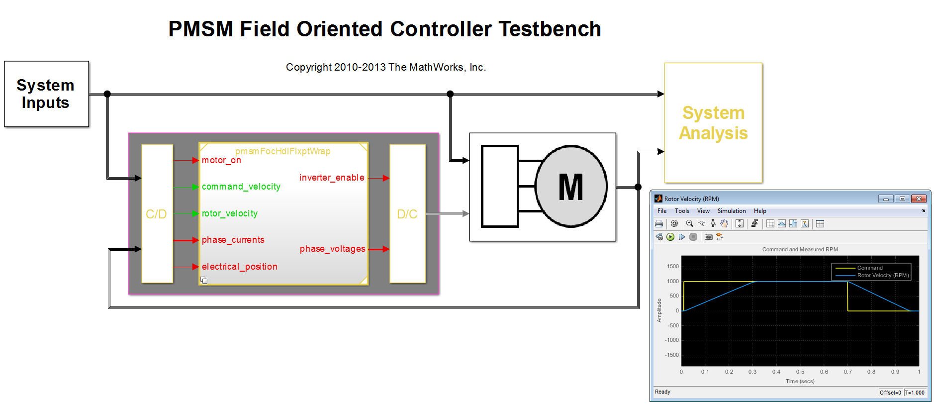
The controller model is packaged into an IP core using the Simulink Workflow Advisor. It exposes a set of AXI-Lite registers that can be used to control the IP’s operation, as well as a set of interface signals for encoder input, current measurement data, inverter control, and internal operations monitoring. All monitoring signals connect to an ADI IP which allows these signals to be monitored from the Linux IIO Scope application. The AXI-Lite registers exposed by the controller IP core can be directly accessed through a UIO driver present in the ADI Linux distribution for Zynq.
The table below lists the exposed AXI-Lite registers.
Register name |
Address |
Data format |
Type |
Description |
|---|---|---|---|---|
|
0x100 |
2-bit word |
W |
Sets the controller’s operation mode: 3 = open loop, 2 = closed loop, 1 = standby. |
|
0x104 |
Signed fixed point 18.8 |
W |
Motor reference speed in rad/s. |
|
0x108 |
Signed fixed point 18.16 |
W |
Proportional gain of the velocity PI controller. |
|
0x10C |
Signed fixed point 18.15 |
W |
Integral gain of the velocity PI controller. |
|
0x110 |
Signed fixed point 18.10 |
W |
Proportional gain of the current PI controller. |
|
0x114 |
Signed fixed point 18.12 |
W |
Integral gain of the current PI controller. |
|
0x118 |
Signed fixed point 18.14 |
W |
Open loop control command bias. |
|
0x11C |
Signed fixed point 18.16 |
W |
Open loop control command gain. |
|
0x120 |
Signed fixed point 18.14 |
W |
Encoder offset. |
|
0x124 |
Signed fixed point 19.14 |
R |
Error between actual electrical position and encoder position. |
Execute the following steps:
Set the FOC controller in open loop mode and wait for the user to start the motor by clicking the Run checkbox in IIO Scope.
Calibrate the encoder readings to remove the offset between the motor’s actual electrical position and the position read from the encoder.
Set the motor’s reference speed.
Start the FOC controller in closed loop mode.
The IP core exposes a set of signals for interfacing with the rest of the system. The table below lists the exposed interface signals.
Signal name |
Dir. |
Width |
Data format |
Description |
|---|---|---|---|---|
|
I |
18 |
Signed fixed point 18.17 |
Phase A current measurement |
|
I |
18 |
Signed fixed point 18.17 |
Phase B current measurement |
|
I |
1 |
Boolean |
Encoder channel A |
|
I |
1 |
Boolean |
Encoder channel B |
|
I |
1 |
Boolean |
Encoder index |
|
O |
1 |
Boolean |
Phase A PWM control signal |
|
O |
1 |
Boolean |
Phase B PWM control signal |
|
O |
1 |
Boolean |
Phase C PWM control signal |
|
O |
32 |
Signed fixed point 32.12 |
Phase A voltage in Volts |
|
O |
32 |
Signed fixed point 32.12 |
Phase B voltage in Volts |
|
O |
32 |
Signed fixed point 32.15 |
Phase A current in Amps |
|
O |
32 |
Signed fixed point 32.15 |
Phase B current in Amps |
|
O |
32 |
Signed fixed point 32.14 |
Rotor mechanical position in radians |
|
O |
32 |
Signed fixed point 32.14 |
Rotor electrical position in radians |
|
O |
32 |
Signed fixed point 32.8 |
Rotor velocity in rad/s |
|
O |
32 |
Signed fixed point 32.15 |
d current in Amps |
|
O |
32 |
Signed fixed point 32.15 |
q current in Amps |
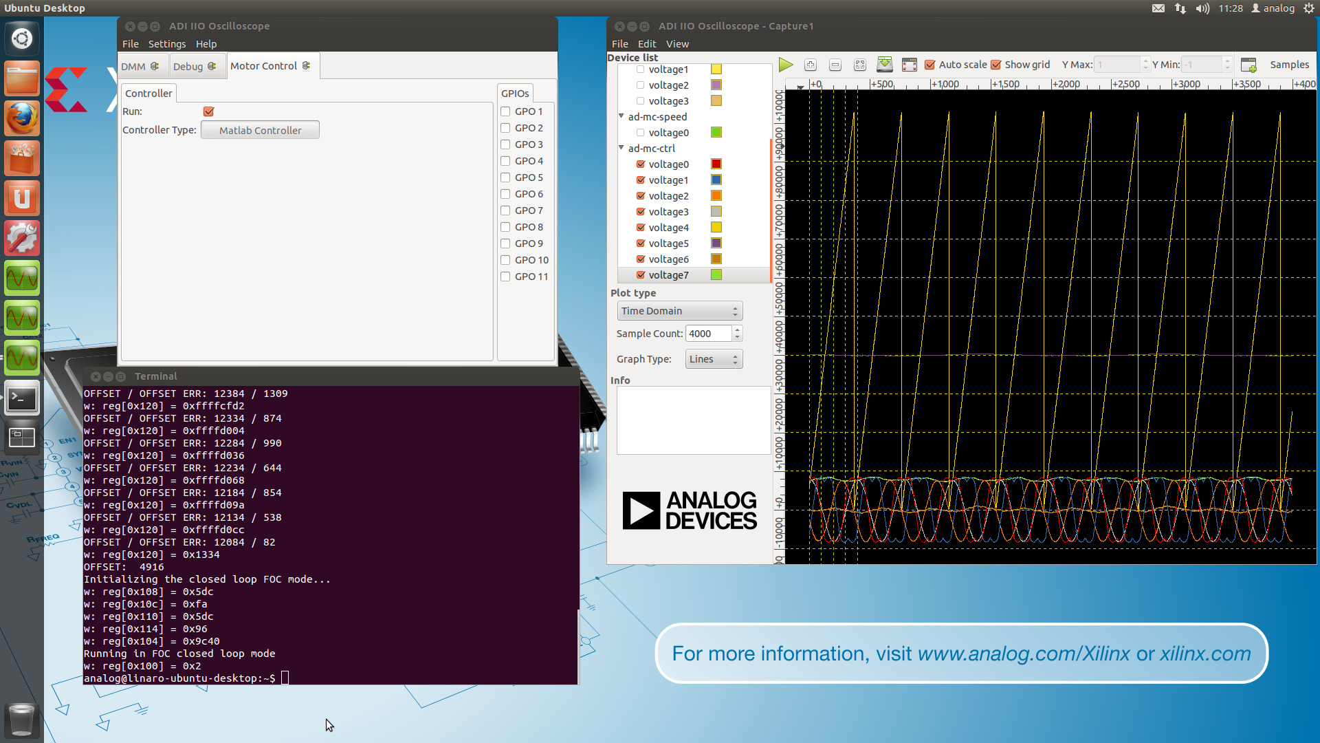
Below is a picture containing the output of the script, the IIO Scope settings, and a controller monitored signals plot.