AD-FMCMOTCON1-EBZ ISE Project with Chipscope
Warning
The AD-FMCMOTCON1-EBZ is a legacy product and is no longer actively supported. This documentation is provided for reference only.
This guide provides some quick instructions on how to setup the AD-FMCMOTCON1-EBZ on either:
Software Tools
Xilinx ISE 14.6
Xilinx Chipscope Pro 14.6
System Setup
To setup the hardware follow the steps described in the Linux on Zynq Quick Start Guide.
The FPGA must be programmed with the top.bit bitstream that results after compiling the ISE project. This has already been done; the bitstream was generated and can be found in the ISE project’s folder. To program the FPGA use the iMPACT tool from Xilinx.
Chipscope Interface
The user interface uses Xilinx Chipscope 14.6. In order to be able to see the plots from sections C and D, the triggers from UNIT:1 and UNIT:2 must be enabled.
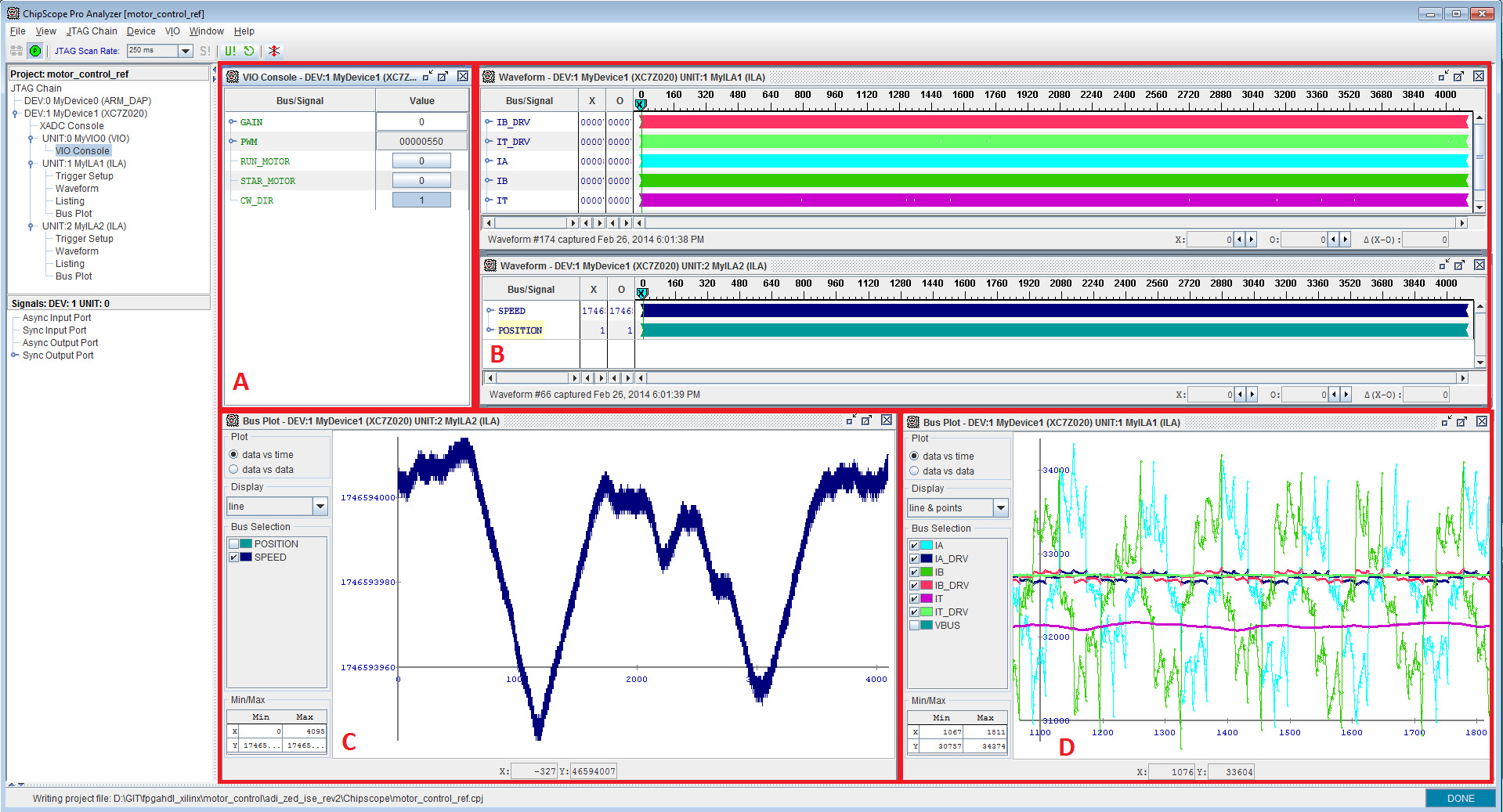
Section A is used for control.
Section B is used for checking the waveform for the currents in the design.
Section C is used to represent graphically the speed of the motor.
Name |
Description |
|---|---|
SPEED |
Time between a change of the HALL sensors state, measured in 100 ns units |
Section D is used to plot the currents and voltages described in section B.