Motor Control Theory
Warning
The AD-FMCMOTCON1-EBZ is a legacy product and is no longer actively supported. This documentation is provided for reference only.
This section provides background on motor drive classifications and the control techniques demonstrated by the AD-FMCMOTCON1-EBZ system.
Electric Motor Drives
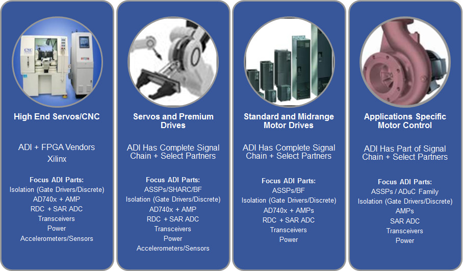
A Motor Drive is a system that varies the motor electrical input power to control the shaft torque, speed, or position. The motor drives can be classified into the following categories:
Application specific drive — designed to run a specific motor in a specific application (e.g., variable speed pump drive).
Standard drive — designed as a general-purpose motor speed controller capable of running a variety of motors within a given power range.
Servo drive — designed to deliver accurate and high dynamic control of position, speed, or torque down to zero speed. Typically used in automation applications.
High performance servos — designed to deliver best in class accuracy and connectivity. Typically used in CNC and pick and place machines.
Market sub-segments in motor control - partners and system value from ADI
Brushed DC Motor Control
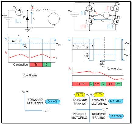
The Brushed DC motor is the simplest type of motor to control, all that needs to be done is to vary the supply voltage and the motor’s speed will vary proportional to the voltage. The most common technique used to vary the applied voltage is called Pulse Width Modulation (PWM), where constant amplitude voltage pulses of varying widths are provided to the motor - the wider the pulse, the more energy transferred to the motor. The frequency of the pulses is high enough that the motor’s inductance averages them, and it runs smooth.
A single transistor and diode can control the speed of a dc motor.
The motor speed (voltage) is proportional to the transistor ON duty cycle.
Positive torque only — passive braking.
An H-bridge power circuit enables four quadrant control:
Forward and reverse motion and braking.
Complementary PWM signals applied to the high and low side switches in the bridge.
Brushless DC Motor Control
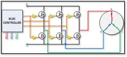
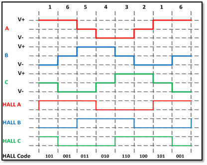
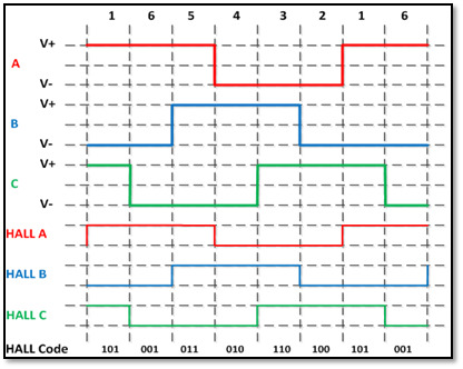
Brushless DC motors windings generate a trapezoidal back EMF synchronized to the position of the rotor magnet. Hall effect sensors are used to detect the rotor magnet position and provide signals indicating the “flat top” portion for each winding’s back EMF.
Star Connection Control
For any one segment, two windings will be in the “flat top” portion of the back EMF and a third winding will be switching between a positive and negative output.
Electronic control leaves one winding open circuit, connects one winding to the lower dc rail, and controls the voltage applied to the third winding using PWM.
The fill factor of the applied PWM controls the speed of the motor.
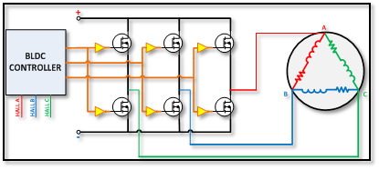
Delta Connection Control
For any one segment, two windings are connected to the positive voltage supply and a third winding is connected to the negative voltage supply.
The fill factor of the applied PWM controls the speed of the motor.
Sensorless control can be achieved by detecting the zero crossings of the BEMF for each phase. Benefits: lower system cost, increased reliability. Drawbacks: BEMF zero crossings can’t be reliably detected at low motor speeds.