Low Voltage Drive Board
Warning
The AD-FMCMOTCON1-EBZ is a legacy product and is no longer actively supported. This documentation is provided for reference only.
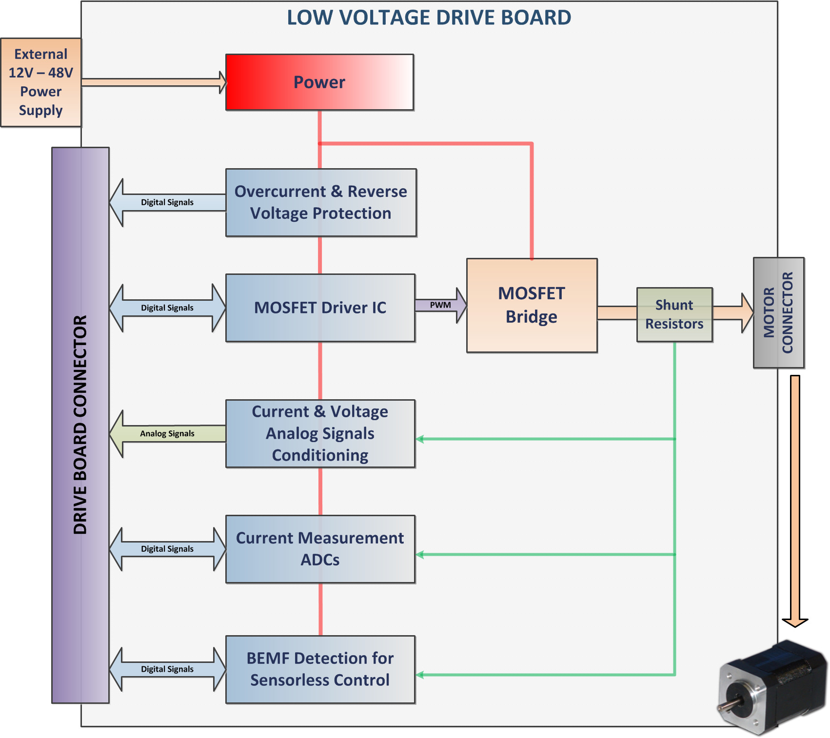
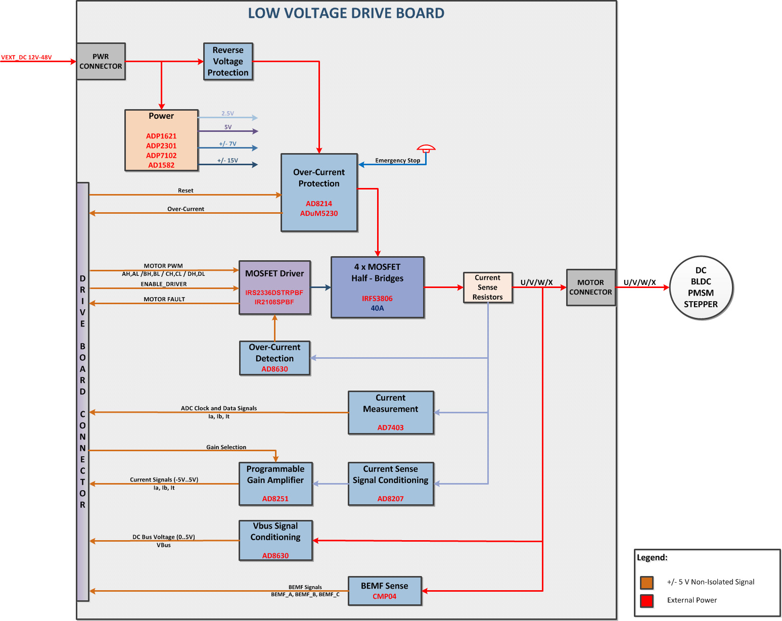
Features and Block Diagram
Drives BLDC, PMSM, Brushed DC, and Stepper motors
Drives motors up to 48 V at 18 A
Integrated over-current protection
Current measurement using isolated ADCs
Bus voltage, phase currents, and total current analog feedback signals
PGAs to maximize the current measurement input range
BEMF zero-crossing detection for sensorless control of PMSM or BLDC motors
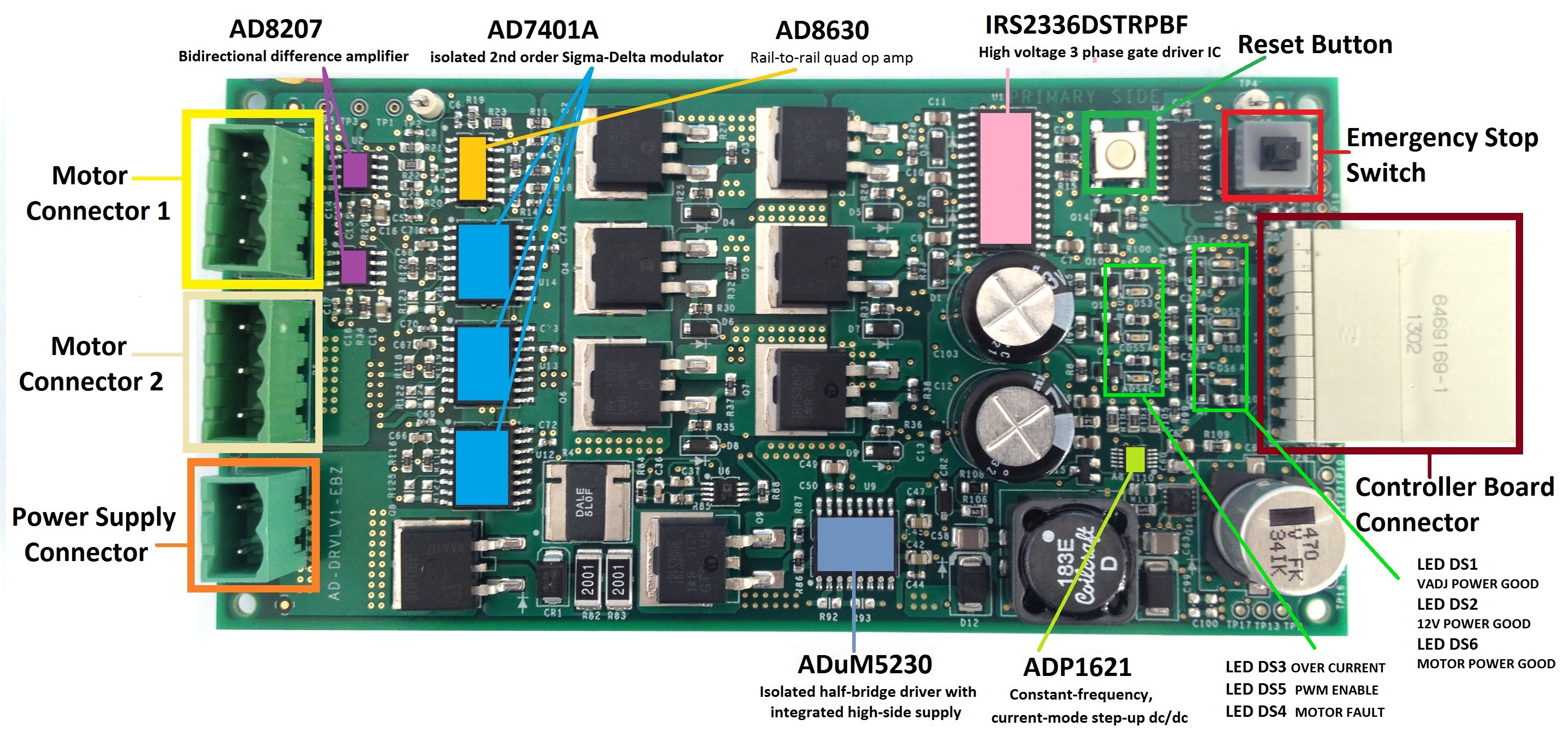
Picture and Main Components
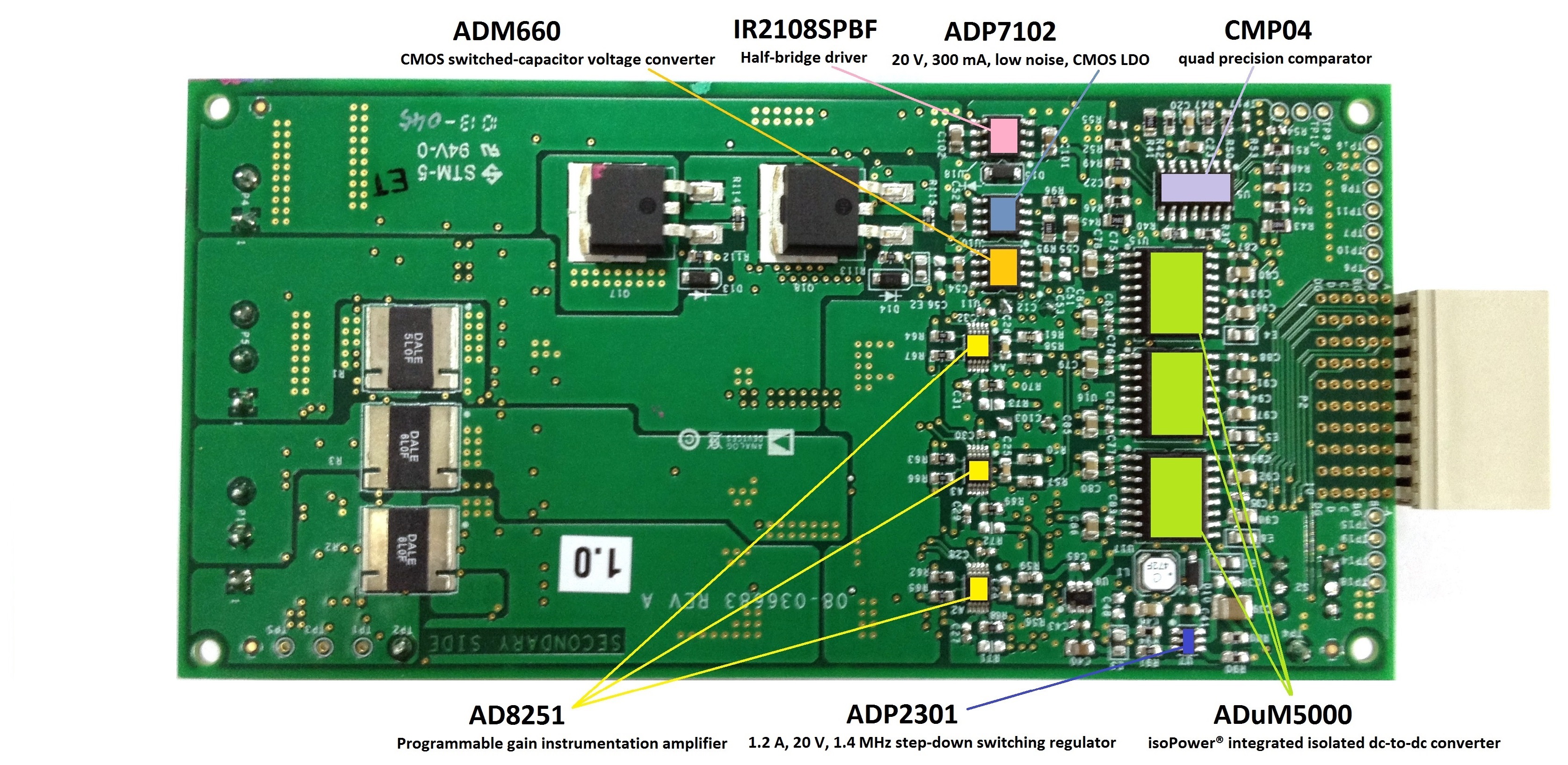
Key Parts
Part |
Description |
|---|---|
Measurement |
|
5 kV rms, isolated 2nd order Sigma-Delta modulator |
|
Zero drift, high voltage, bidirectional difference amplifier |
|
10 MHz, 2 nV/√Hz, programmable gain instrumentation amplifier |
|
Zero drift, single-supply, rail-to-rail quad op amp |
|
Power |
|
isoPower® integrated isolated dc-to-dc converter |
|
Constant-frequency, current-mode step-up dc/dc controller |
|
1.2 A, 20 V, 1.4 MHz non-synchronous step-down switching regulator |
|
20 V, 300 mA, low noise, CMOS LDO |
|
MOSFET Drivers |
|
Isolated half-bridge driver with integrated high-side supply |
|
IRS2336DSTRPBF |
High voltage 3-phase gate driver IC |
Connectors
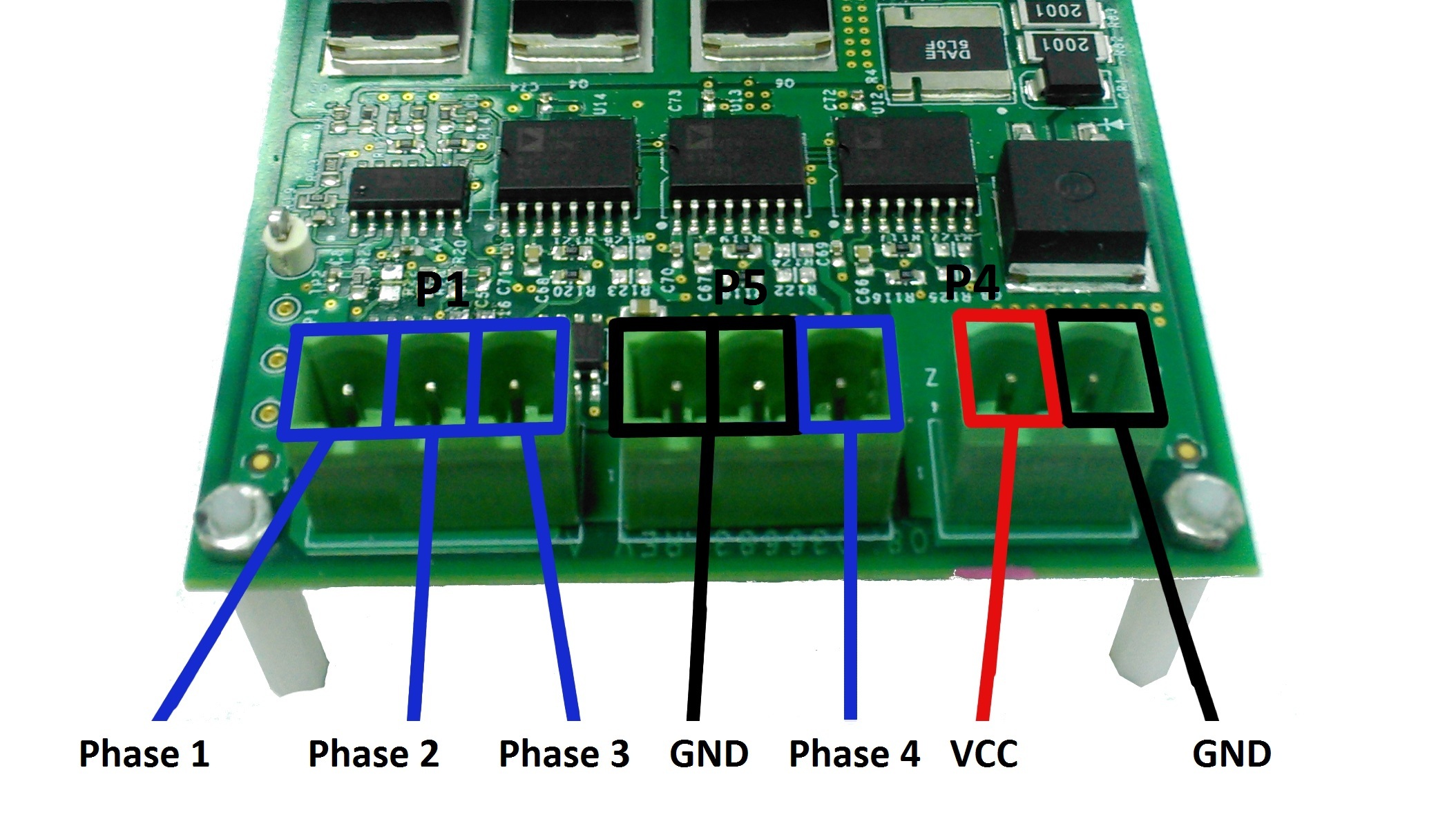
Power connector
Connector P4 supplies 12–48 VDC to the drive board.
The polarity is indicated in the picture above.
BLDC / Stepper motor connector
For BLDC motors use connector P1 (Phase 1, 2, and 3).
For Stepper motors use connector P1 and pin 3 of P5 (Phase 1, 2, 3, and 4).
Switches
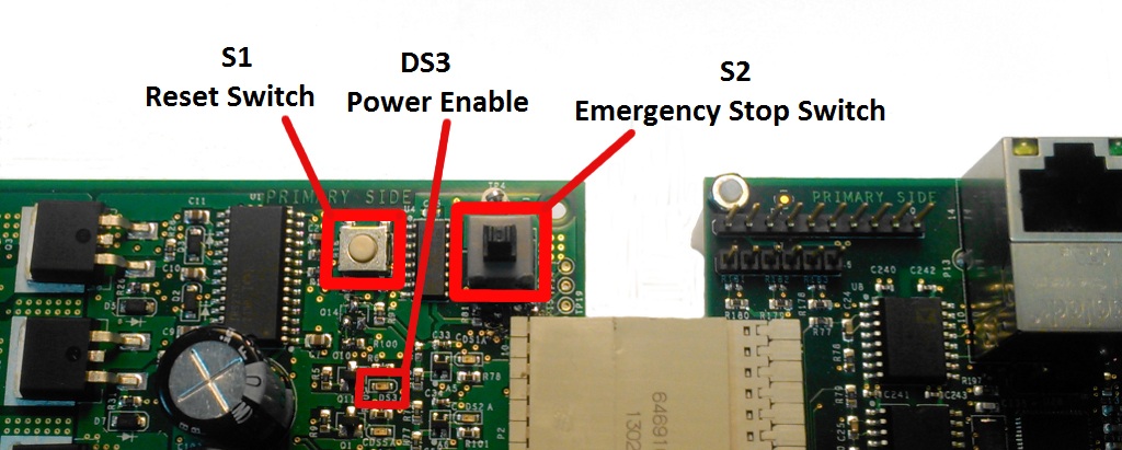
Emergency Stop Switch
S2 is a latching emergency stop switch.
If triggered, the supply for the power stage is turned off.
LED DS3 indicates the state of the power stage.
Reset Switch
S1 is a reset switch for the emergency stop latch.
Pressing S1 when S2 is off turns the power stage on.
LEDs
LED |
Description |
|---|---|
DS1 |
Vadj Power Good |
DS2 |
12V Power Good |
DS3 |
Over Current |
DS4 |
Motor Fault |
DS5 |
PWM Enable |
DS6 |
Motor Power Good |
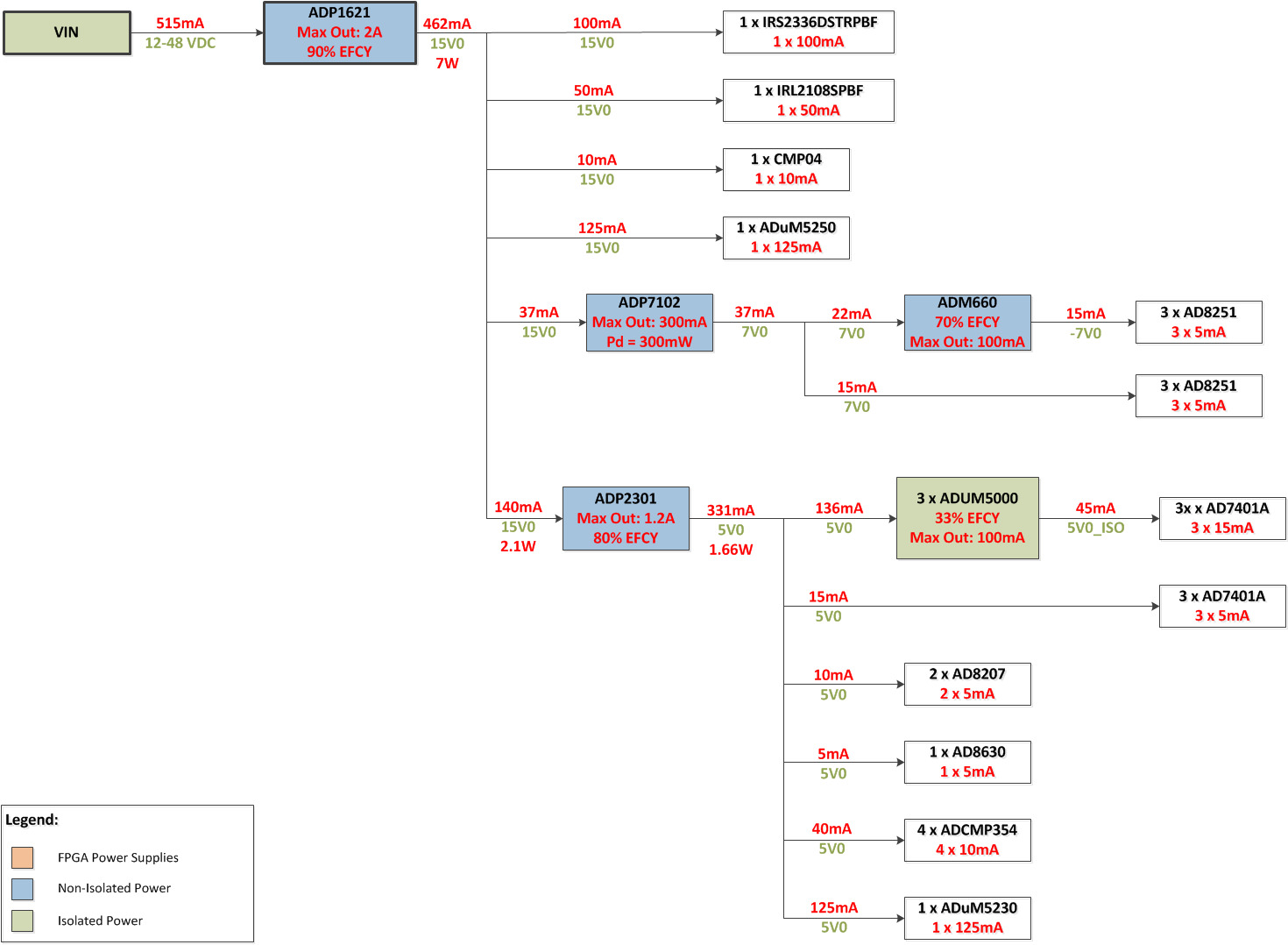
Power Map
Motor Driver Interface
The IRS2336D three-phase gate driver IC provides the following interface signals:
3 pairs of complementary PWM signals with inverted logic
PWM frequency up to 150 kHz
Hardware integrated dead-time protection
Enable signal to start / stop the driver
Fault signal from the driver