AD-FMCMOTCON1-EBZ Signal Measurement Chain
Warning
The AD-FMCMOTCON1-EBZ is a legacy product and is no longer actively supported. This documentation is provided for reference only.
The motor control system allows the measurement of Ia (phase A current), Ib (phase B current), It (total current), and Vbus using signal chains that involve components from both the controller and low voltage driver boards.
Ia, Ib Measurement Signal Chain
The Ia and Ib currents are sensed using 6 mΩ shunt resistors. There are two possible measurement paths for the case where the ADC can be placed close to the shunt resistor and for the case where it cannot. Both aim to achieve the best measurement accuracy.
Case 1: ADC placed in proximity of the shunt resistor
The signal path between the shunt resistor and the ADC is very short and less prone to noise coupling.
The small differential voltage on the shunt resistor is measured directly with the AD7401 isolated ΣΔ modulator without extra signal conditioning circuitry.
The digital data and clock signals travel the entire length of the drive and controller boards to the FPGA. Since the analog signal was digitized close to the source, there are no concerns related to measurement quality.
Formula:
where \(counts = \text{ADC value},\ RS = 6\,m\Omega,\ ADCrange = 320\,\text{mV},\ ADCbits = 16\).
Case 2: ADC not placed in proximity of the shunt resistor
The signal path between the shunt resistor and the ADC is long and prone to noise coupling from the switching power stage and the motor itself.
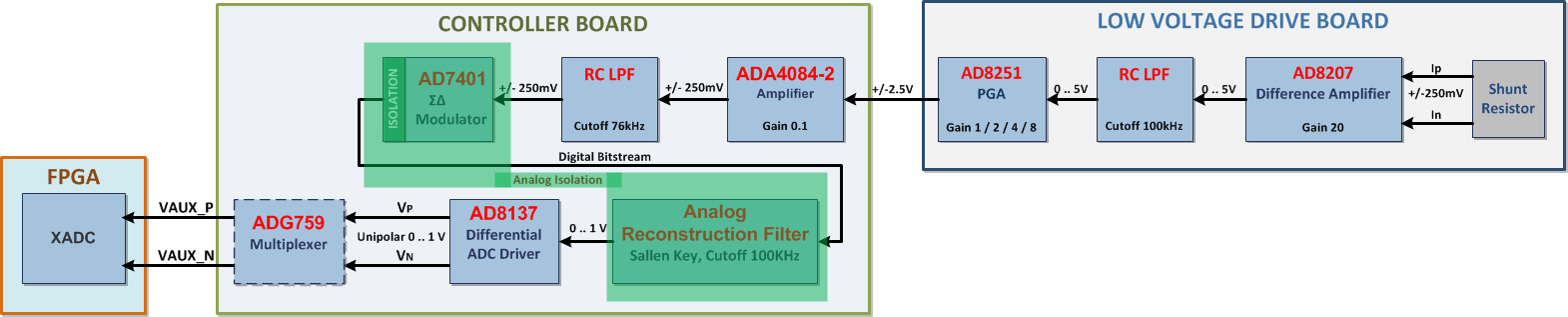
The small differential voltage on the shunt resistor is amplified on the drive board with the AD8207 difference amplifier placed close to the shunt, boosting the 0-250 mV input range to 0-5 V to minimize coupled noise.
A programmable amplification stage using the AD8251 PGA ensures the ADC always receives signals scaled to fit its input range.
The amplified analog signals pass through the connector (with per-signal shielding) to the controller board.
On the controller board, the ADA4084-2 amplifier attenuates the ±2.5 V input range to ±250 mV for the AD7401 ΣΔ modulator.
Formula:
where \(counts = \text{ADC value},\ RS = 6\,m\Omega,\ ADCrange = 320\,\text{mV},\ ADCbits = 16,\ CTRLgain = \tfrac{1}{10},\ DRVgain = 20,\ PGAgain \in \{1, 2, 4, 8\}\).

Ia, Ib XADC Measurement Signal Chain
The Ia and Ib XADC measurement chain uses the entire path of the regular chain and adds a Sallen-Key analog reconstruction filter (implemented with AD8646 op-amps) on the controller board after the AD7401 ΣΔ modulator. The combination of the isolated ΣΔ modulator and the reconstruction filter provides a convenient low-cost method of achieving analog isolation for the XADC input signals.
It Measurement Signal Chain
The It current is sensed using a 5 mΩ shunt resistor. There are two possible measurement paths, identical in principle to the Ia/Ib chains.
Case 1: ADC placed in proximity of the shunt resistor
Very short, low-noise signal path.
Differential voltage measured directly with the AD7401 isolated ΣΔ modulator.
Formula:
where \(counts = \text{ADC value},\ RS = 5\,m\Omega,\ ADCrange = 320\,\text{mV},\ ADCbits = 16\).
Case 2: ADC not placed in proximity of the shunt resistor
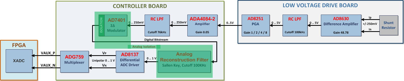
The differential voltage is amplified on the drive board with the AD8630 difference amplifier to 0-5 V.
A programmable AD8251 PGA stage scales the signal for the ADC input range.
Shielded connector transfers the signal to the controller board.
The ADA4084-2 on the controller board attenuates from 0-5 V to 0-250 mV for the AD7401 ΣΔ modulator.
Formula:
where \(counts = \text{ADC value},\ RS = 5\,m\Omega,\ ADCrange = 320\,\text{mV},\ ADCbits = 16,\ CTRLgain = \tfrac{1}{10},\ DRVgain = 20,\ PGAgain \in \{1, 2, 4, 8\}\).

It XADC Measurement Signal Chain
The It XADC measurement chain uses the entire path of the regular It chain and adds a Sallen-Key analog reconstruction filter (AD8646) after the AD7401 ΣΔ modulator.
Vbus Measurement Signal Chain
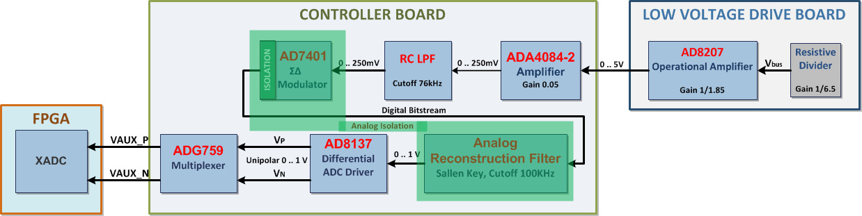
Vbus sensing is done on the drive board using a resistive divider and an attenuation circuit implemented with the AD8207 op-amp. The total gain of this stage is 0.83, giving an output range of 0-5 V. The signal passes through the connector to the controller board, where the ADA4084-2 attenuates from 0-5 V to 0-250 mV for the AD7401 ΣΔ modulator.
Formula:
where \(counts = \text{ADC value},\ ADCrange = 320\,\text{mV},\ ADCbits = 16,\ DRVgain = \tfrac{5}{60},\ CTRLgain = \tfrac{1}{10}\).

Vbus XADC Measurement Signal Chain
The Vbus XADC measurement chain uses the entire path of the regular Vbus chain and adds a Sallen-Key analog reconstruction filter (AD8646) after the AD7401 ΣΔ modulator.
Note
Current chain formula variable summary:
For RS = 6 mΩ (Ia, Ib): \(counts = \text{ADC value},\ RS = 6\,m\Omega,\ ADCrange = 320\,\text{mV},\ ADCbits = 16,\ CTRLgain = \tfrac{1}{10},\ DRVgain = 20,\ PGAgain \in \{1, 2, 4, 8\}\)
For RS = 5 mΩ (It): \(counts = \text{ADC value},\ RS = 5\,m\Omega,\ ADCrange = 320\,\text{mV},\ ADCbits = 16,\ CTRLgain = \tfrac{1}{10},\ DRVgain = 20,\ PGAgain \in \{1, 2, 4, 8\}\)