EVAL-AD7124-8-PMDZ Hardware Guide
Set-up Procedures
After reviewing the prerequisites, set up the evaluation board as detailed in this section.
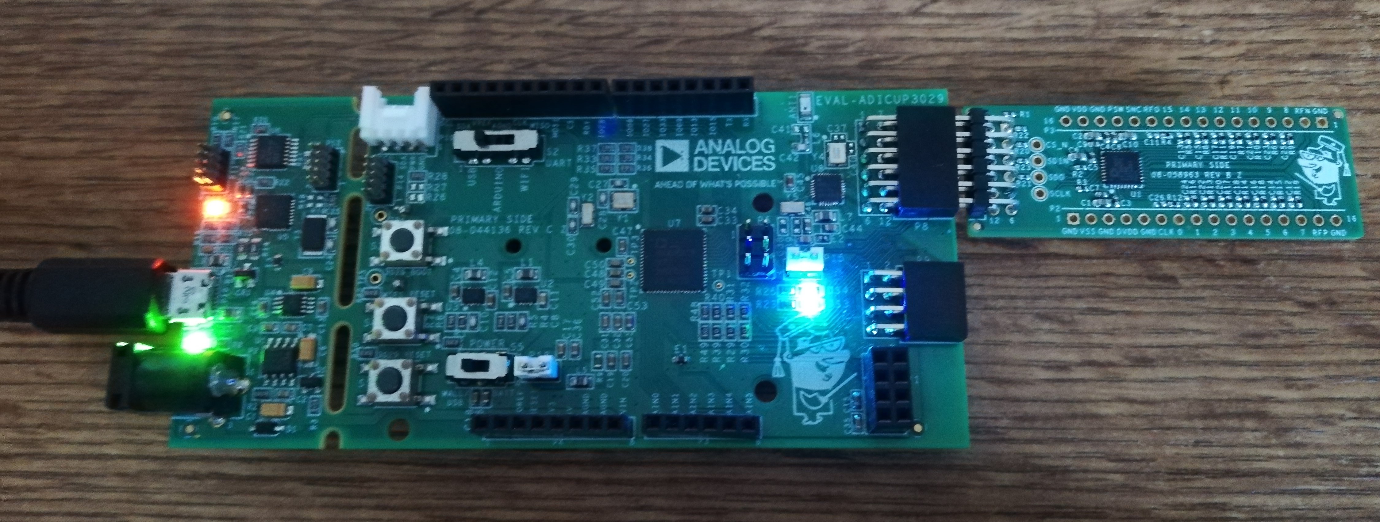
Connect the EVAL-AD7124-8-PMDZ board to the Pmod connector on the EVAL-ADICUP3029.
Connect a micro-USB cable from the P10 connector of the EVAL-ADICUP3029 to your computer.
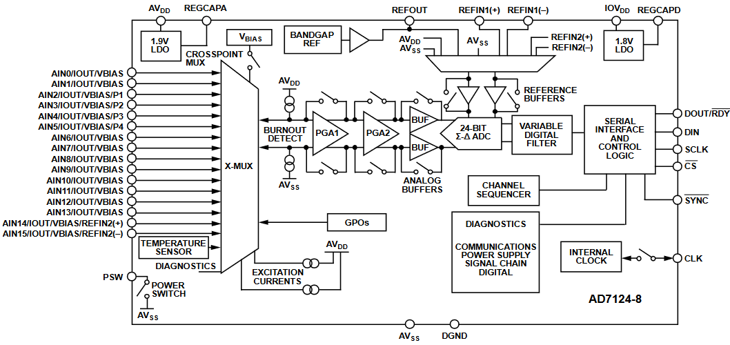
Block Diagram
On Board Connections
Connector P1: SPI Pmod
The digital communication on the EVAL-AD7124-8-PMDZ is accomplished using a standard expanded SPI Pmod port.
Description |
Pin(s) |
|---|---|
CS |
1 |
SDIN |
2 |
SDO |
3 |
SCLK |
4 |
GND |
5, 11 |
IOVDD |
6, 12 |
SDO |
7 |
Open or SDO |
8 |
Open or SDO |
9 |
Open or SDO |
10 |
Connector P2: Analog I/O
Description |
Pin(s) |
|---|---|
GND |
1, 3, 5, 16 |
AVSS |
2 |
IOVDD |
4 |
CLK |
6 |
AIN0 |
7 |
AIN1 |
8 |
AIN2 |
9 |
AIN3 |
10 |
AIN4 |
11 |
AIN5 |
12 |
AIN6 |
13 |
AIN7 |
14 |
REFIN1(+) |
15 |
Connector P3: Analog I/O
Description |
Pin(s) |
|---|---|
GND |
1, 14, 16 |
REFIN1(-) |
2 |
AIN8 |
3 |
AIN9 |
4 |
AIN10 |
5 |
AIN11 |
6 |
AIN12 |
7 |
AIN13 |
8 |
AIN14 |
9 |
AIN15 |
10 |
REFOUT |
11 |
SYNC |
12 |
PSW |
13 |
AVDD |
15 |
Note
Not all pins require inputs. The following pins are exposed and can be used if necessary, but they must first be disconnected from their default onboard connection if that connection exists: AVSS, AVDD, REFIN1(+), REFIN1(-), CLK, REFOUT, SYNC, PSW. Please refer to the AD7124-8 datasheet to learn more about their function.
Hardware Link Options
Solder Jumpers
Eight solder jumpers are available at the bottom of the board to change the operating modes. See the schematic for more details.
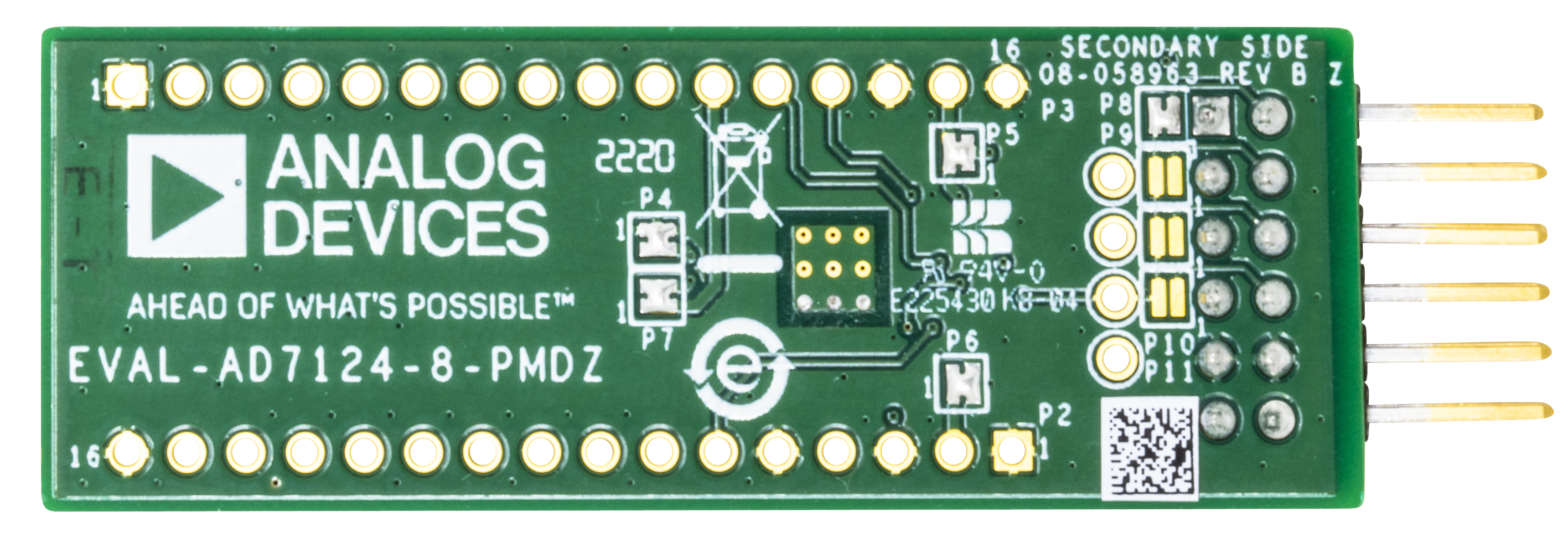
Description and default connection |
Solder Jumper |
Default Position |
|---|---|---|
ADC REFIN1(-) connection (connect GND and P3 pin 2) |
P4 |
Shorted |
ADC REFIN1(+) connection (connect ADC REFOUT and P2 pin 15) |
P7 |
Shorted |
ADC AVDD connection (connect ADC IOVDD and P3 pin 15) |
P5 |
Shorted |
ADC AVSS connection (connect GND and P2 pin 2) |
P6 |
Shorted |
ADC SDO connection (connected to P1 pin 7, default) |
P8 |
Shorted |
ADC SDO connection (connected to P1 pin 8) |
P9 |
Open |
ADC SDO connection (connected to P1 pin 9) |
P10 |
Open |
ADC SDO connection (connected to P1 pin 10) |
P11 |
Open |
Test Points
Four test points are available to probe the SPI interface.
Power Supplies
The EVAL-AD7124-8-PMDZ is powered through the Pmod connector (IOVDD pins). The AD7124-8 operates with a single analog power supply from 2.7 V to 3.6 V. By default, AVDD is connected to IOVDD through solder jumper P5.
Design and Integration Files
Download
EVAL-AD7124-8-PMDZ Design & Integration Files
Schematic
PCB Layout
Bill of Materials
Allegro Project