EVAL-ADICUP3029 Quick Start
All the products described on this page include ESD (electrostatic discharge) sensitive devices. Electrostatic charges as high as 4000V readily accumulate on the human body or test equipment and can discharge without detection. Although the boards feature ESD protection circuitry, permanent damage may occur on devices subjected to high-energy electrostatic discharges. Therefore, proper ESD precautions are recommended to avoid performance degradation or loss of functionality. This includes removing static charge on external equipment, cables, or antennas before connecting to the device.
This guide describes how to use the EVAL-AD7124-8-PMDZ Pmod board with the EVAL-ADICUP3029 development platform using the ADuCM3029_demo_ad7124_8PMDZ demo project.
The demo provides a CLI-based interface to control the AD7124-8 ADC, showcasing the flexibility of the AD7124 in choosing inputs, filters, and different ranges for the available 16 channels.
General description
The initial configuration engages all inputs in a mix of differential and single-ended channels:
Channels 0–7: AIN0/AIN1, AIN2/AIN3, …, AIN14/AIN15 (differential)
Channels 8–15: AIN0/AGND, AIN1/AGND, …, AIN7/AGND (single-ended)
By default only channel 0 is active, but this can be adjusted using the CLI commands described below. All channels initially use configuration register 0 (sinc4 filter, widest PGA range, maximum sample rate).
Prerequisites
See Prerequisites for the full list.
Hardware:
Micro USB to USB cable
PC or laptop with a USB port
Software:
CrossCore Embedded Studio (2.9.1 or higher)
ADuCM302x DFP (3.2.0 or higher)
ADICUP3029 BSP (1.1.0 or higher)
Serial terminal program (e.g., PuTTY, Tera Term)
Setting up the hardware
Connect the EVAL-AD7124-8-PMDZ board to the Pmod connector on the EVAL-ADICUP3029.
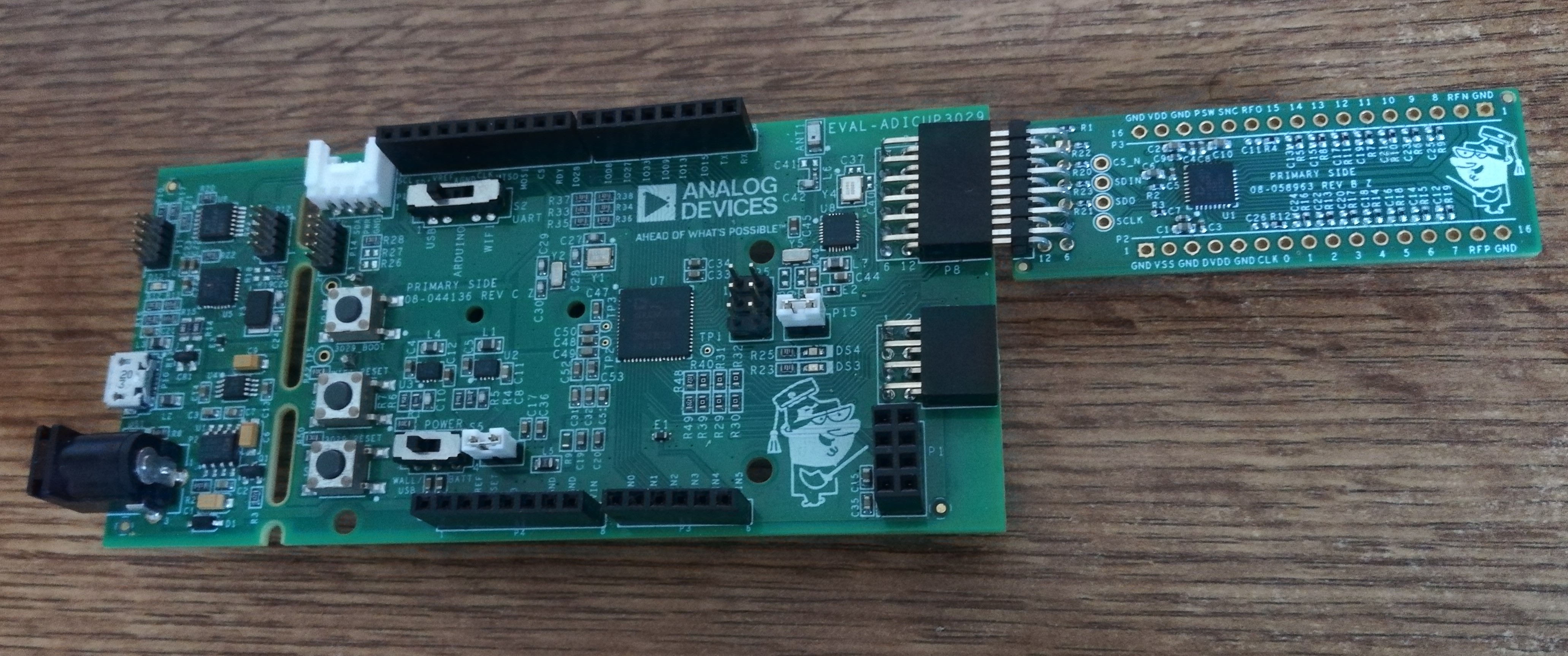
Figure 1 EVAL-AD7124-8-PMDZ and EVAL-ADICUP3029 before connection
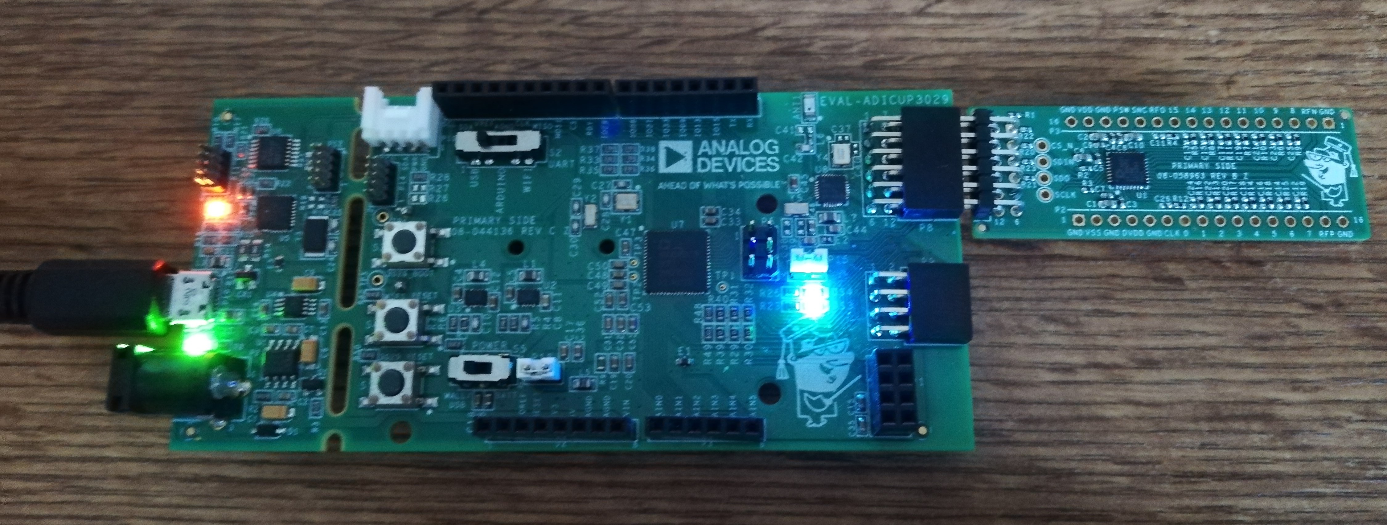
Connect a micro-USB cable to the P10 connector of the EVAL-ADICUP3029 and connect it to a computer. The final setup should look similar to the picture below.
Serial terminal setup
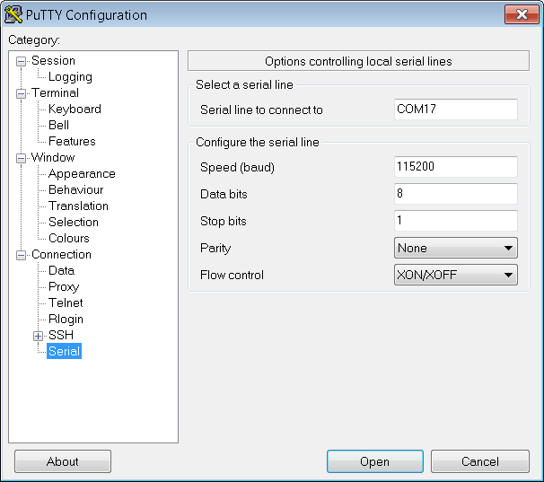
A serial terminal is used to interact with the demo firmware over USB. The default serial settings are:
Baud rate: 115200
Data bits: 8
Parity: None
Stop bits: 1
Flow control: None
Example setup using PuTTY
Plug in the EVAL-ADICUP3029 using a micro-USB cable.
Wait for the device driver to install on your PC.
Open Device Manager and find the assigned COM port.
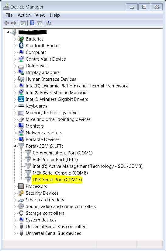
Open PuTTY and configure the serial settings:
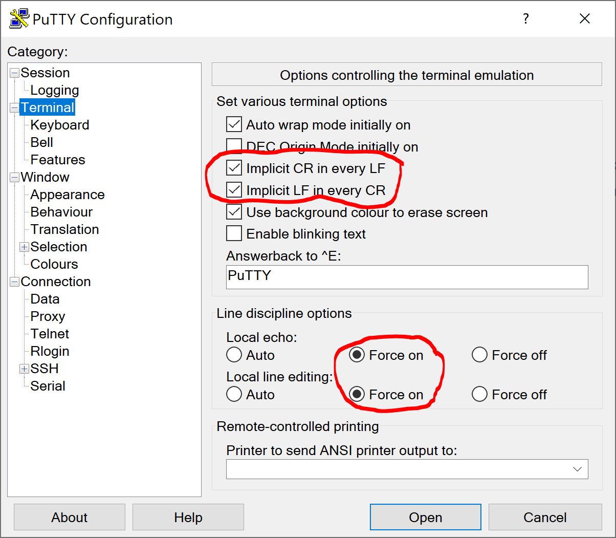
Under the Terminal category, enable Implicit CR in every LF and Implicit LF in every CR. Enable local echo and line editing.
Click Open to start the terminal session.
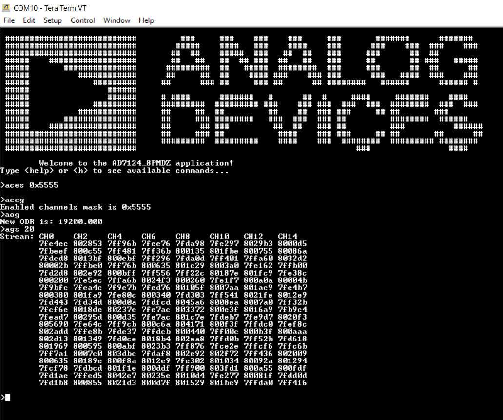
Available commands
Type help or h after the initial calibration sequence to display the list of available commands.
Obtaining the software
There are two ways to program the EVAL-ADICUP3029:
Drag and drop the prebuilt .Hex file to the DAPLINK USB drive (easiest method for quick evaluation)
Build from source using CrossCore Embedded Studio (allows customization)
Download
Prebuilt AD7124-8 Pmod Hex File:
Complete AD7124-8 Pmod Source Files:
How to use the tools
The official tool for use with the EVAL-ADICUP3029 is CrossCore Embedded Studio. For more information on downloading the tools and a quick start guide, see the Tools Overview page.
For importing existing projects, see How to import existing projects into your workspace.
For configuring debug sessions, see How to configure the debug session.
Project structure
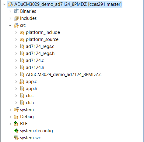
The application contains the platform drivers with sources in platform_source and headers in platform_include. In the src root directory there is the AD7124 driver as found on GitHub, but with a custom initialization vector in the ad7124_regs module.