Digital IO
Video guide:
General description

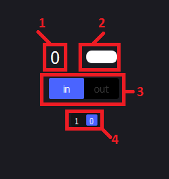
Digital channel number - the physical pin of the M2K
Channel input state - indicates the input read by the M2K
Channel direction - indicates whether the channel is set to input/output
Channel output state - indicates the output value configured of the M2K
Use Cases
IO operation

Run instrument
Connect digital channel 0 to channel 7
Start digital IO instrument
Monitor channel 0 using voltmeter/scope/logic analyzer
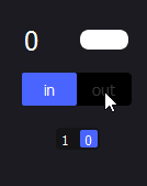
Set channel 0 as output by clicking the direction button Channel 7 input state is the same as channel 0 output state Voltmeter shows the same state (5V/0V) as channel 0 output state
Change channel 0 output state by clicking it (multiple times) Channel 7 input state is the same as channel 0 output state Voltmeter shows the same state (5V/0V) as channel 0 output state
Grouped operation
Make the following connections
Channel 0 → Channel 8
Channel 1 → Channel 9
Channel 2 → Channel 10
Channel 3 → Channel 11
Channel 4 → Channel 12
Channel 5 → Channel 13
Channel 6 → Channel 14
Channel 7 → Channel 15
Start digital IO instrument
Also monitor these connections with a logic analyzer (use breadboard to split the connection)
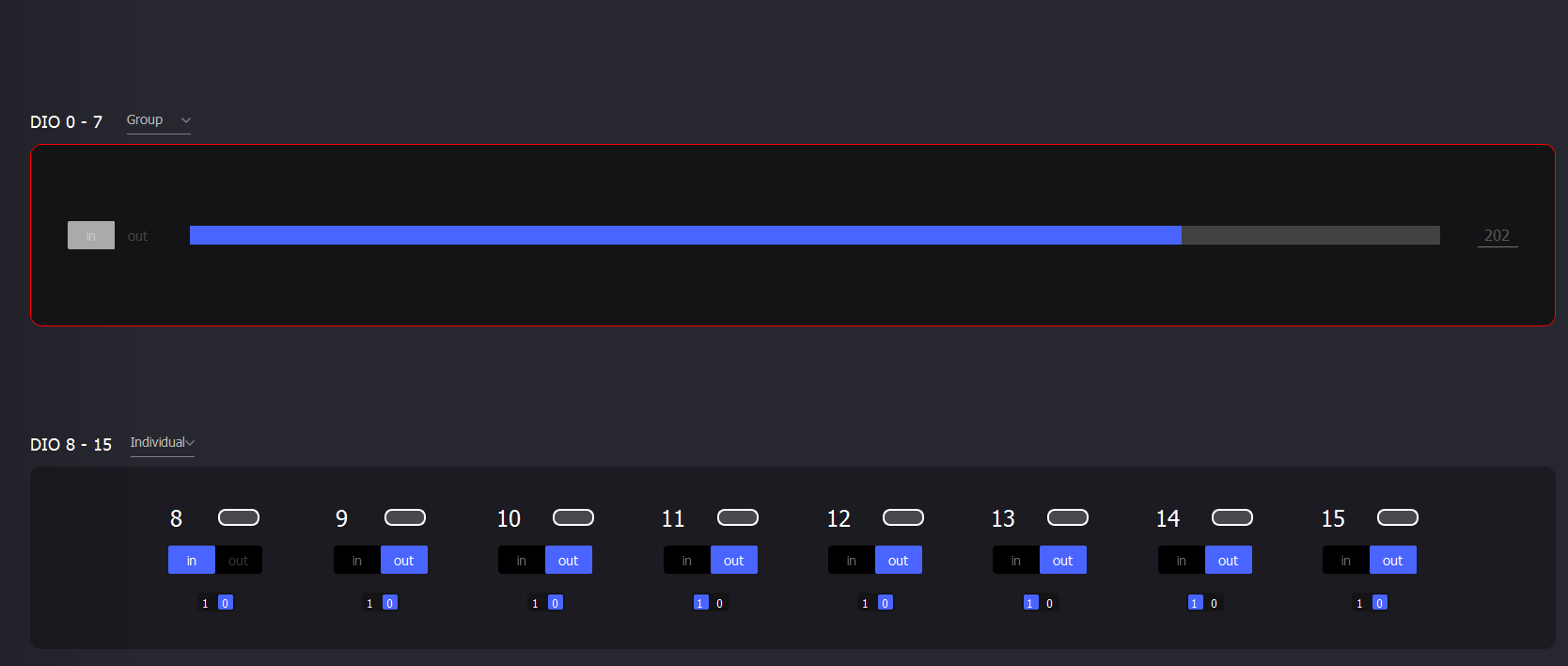
Set DIO 0-7 to Grouped interface
Set all channels DIO8-15 to output
Set each DIO8-15 output states at random
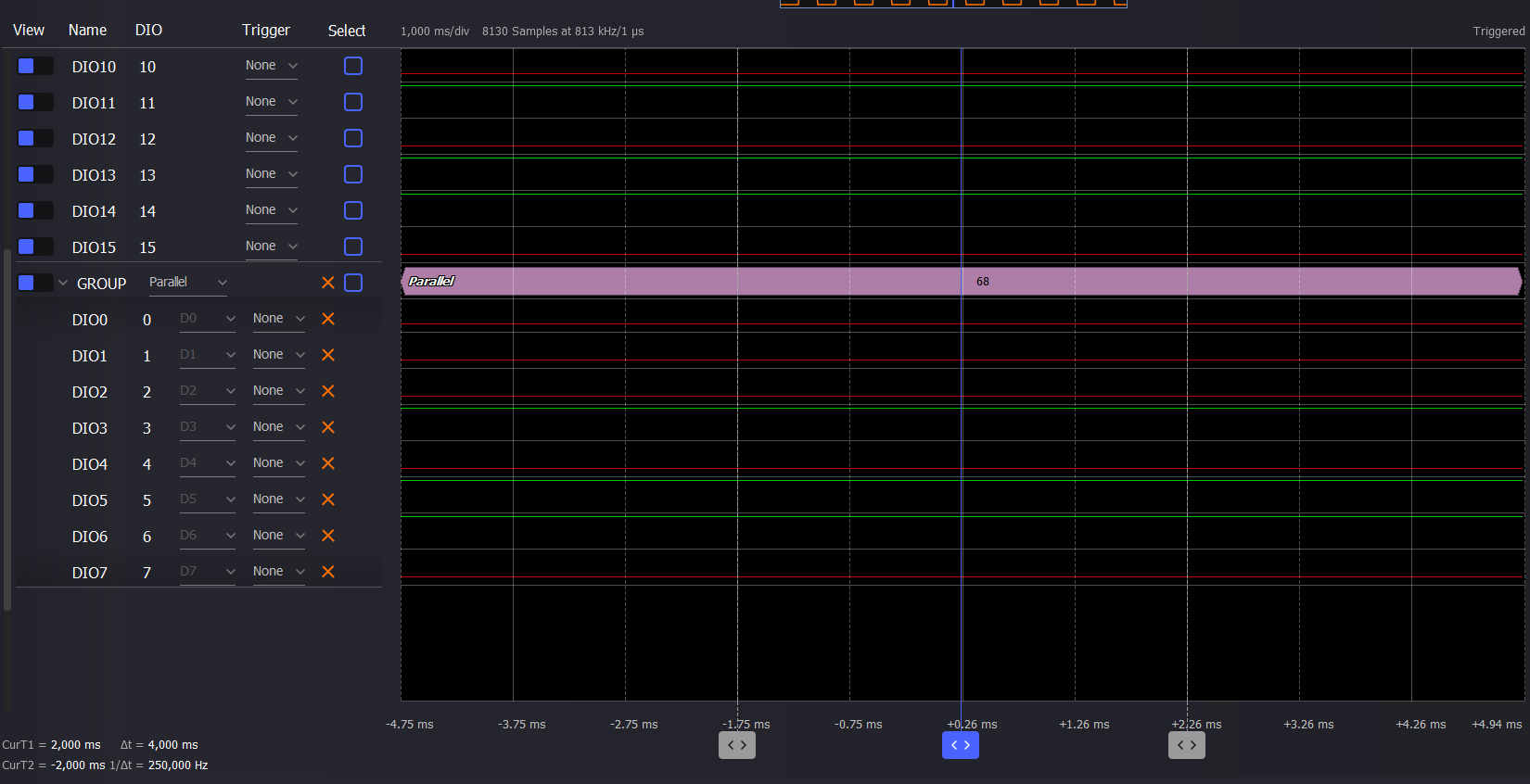
DIO 0 – 7 grouped value should be the binary value of channels 8-15. Logic analyzer should show the same results
Set all channels 8-15 to input
Set Group direction to output
Set Group value to a random value
Channels 8-15 input state should represent that value in binary
Logic analyzer should show the same results

Interaction with pattern generator
Start digital IO instrument
Generate clock signals on channels 0 and 8
In the digitalIO the group as well as channel 8 should have a red highlight indicating that the pattern generator has ownership of the channels.
The user cannot interact with those channels. Logic analyzer shows clock signal correctly generated at channels 0 and 8
Connect channel 10 to channel 11
Set channel 10 as output and channel 11 as input
Modify channel 10 output state
Channel 11 input state follows channel 10 output state
Rest of the channels work properly. The user can set direction and output state and can read input state
While running, set a clock signal on channel 10 in the pattern generator Channel 10 has a red highlight, the user cannot interact with it anymore. Channel 11 input state might flicker indicating that a signal can be read from channel 11.
Logic analyzer shows a new clock signal generated at channel 10 which can also be read on channel 11

Stop the pattern generator
Red highlight is removed from the digitalIO, the channels now work properly.