Pattern Generator
Video guide:
Introduction
The Power Supply instrument is the last item in the Scopy instrument menu list, by default, displayed at the far left of the Scopy window.
The pattern generator instrument can be used to generate output from the M2K with user configurable parameters. It consists of 3 parts:
Channel handles
Signals Plot
Control Panel
The buttons on top of the pattern generator are:
The Run button starts the pattern generation.
The Single button starts a single shot generation.
The gearwheel button activates the general settings menu in the control panel.
The sliders button activates the pattern settings menu in the control panel.
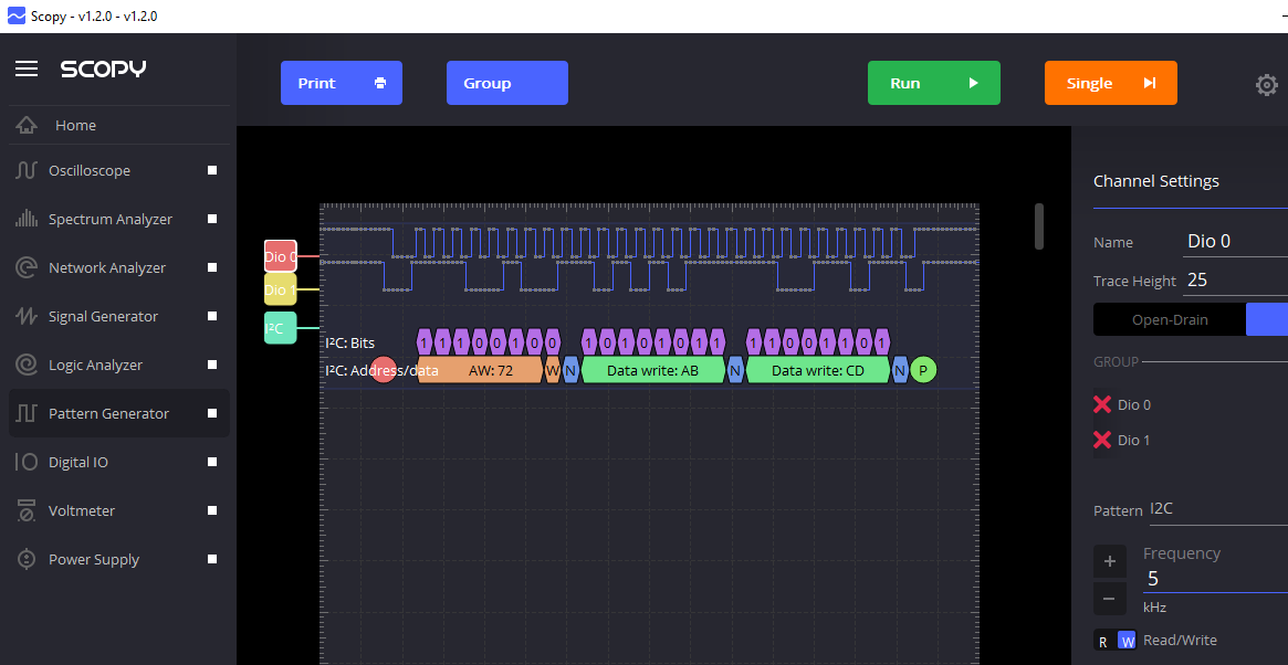
The plot shows a preview of the generated signals by the pattern generator. For the enabled channels, the generated waveform is shown. For channel groups (groups of one or more channels) a “decoder” is displayed and has the purpose to graphically represent the binary value of the channel group. The channel enumerator panel lists all available channels on the device, and allows the user to enable them.
The user can enable channels by clicking the blue checkbox button, setting the channel as an output. By double clicking the channel the channel settings for it will be shown
In the channel settings the name, trace height are displayed. If the channel is part of a group, then the channels in the group are shown and can be removed by clicking the red X button or changed in order using the drag widget. The pattern for this channel/ channel group can be changed and the corresponding pattern settings are displayed. To group a set of channel the same mechanism as in the Logic Analyzer is used. Click the group button (it becomes “done”) select all the channels you want to have in a group, then click the done button. The currently implemented patterns are:
Clock – generates a clock signal having user selectable frequency, phase and duty cycle.
Number - generates a user selectable number
Random – generates random values at a user selectable frequency.
Binary Counter – generates a binary counter on the channels in the channel group.
UART – generates a UART message
SPI - generates a SPI message
I2C - generates an I2C message
Gray Counter - generates a gray counter on the channels in the channel group
Import - imports a CSV file and outputs it’s content
Use cases
Enable & run one channel
Enable channel 0 - select it and enable the clock pattern
Start pattern generator
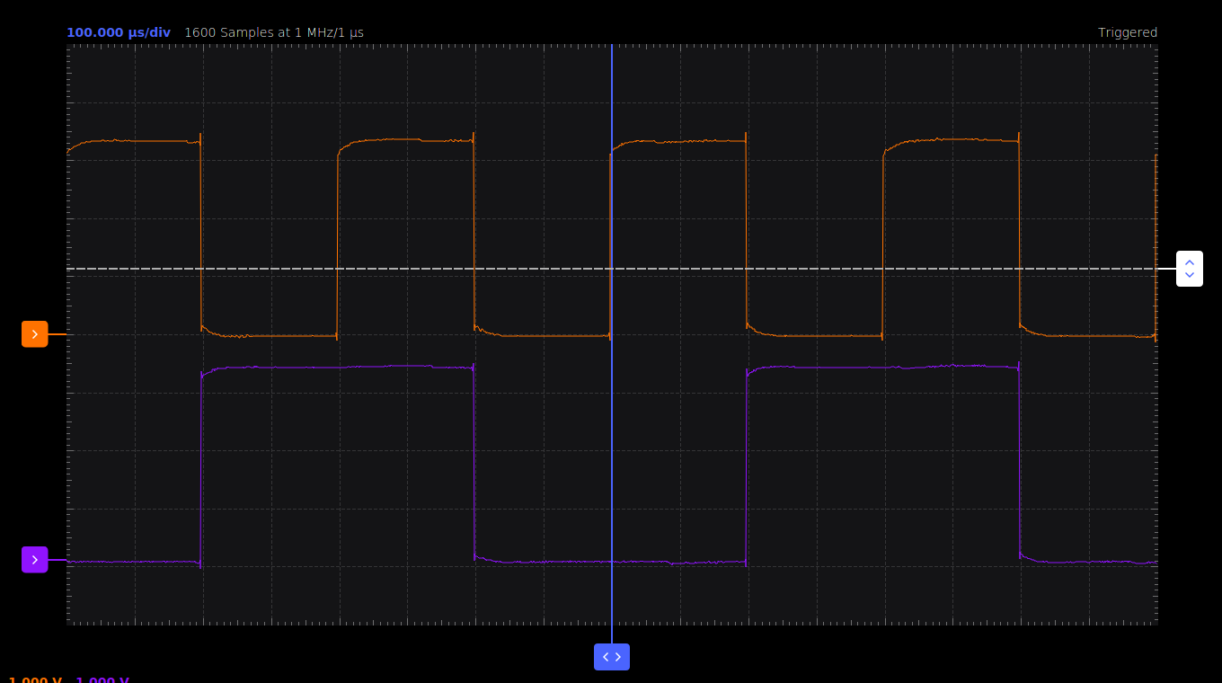
Connect channel 0 to the oscilloscope
Stop pattern generator
Modify parameters - set frequency to 1MHz, 70% duty cycle
Run pattern generator
Create a 4 channel binary counter
- 3.1. Select multiple channels (Selecting a channel is done by double
clicking the handle of the channel on the left side of the plot). Enable multiple channels from the channel enumerator
3.2. Create group Group this 4 channels together
3.3. Select Binary Counter pattern
3.4. The plot should resemble a binary counter
3.5. Start pattern generation
3.6. Using the scope verify channels 0 and 1
- 3.7. Using the Scopy’s logic analyzer (or an external tool) verify channels
0,1,2,3
Change settings while running
Channels can be modified/enabled/disabled while running. The pattern generator will reconfigure and resume running the patterns. While reconfiguring, all pins of the M2K will be taken high impedance in the meantime.
Single-shot generation
Select single

Clicking single shot will generate a single buffer and then switch all pins to high impedance.
Special patterns
Enable a channel and set UART pattern
Set parameters 9600, 8 bits, 1 stop bit, no parity, text “HELLO”
Select channel 15 only and group with selected ( this will create a one-channel group with decoder) The UART decoder should pop up over channel 15
Monitor the channel in the logic analyzer. Use UART decoder. Alternatively use a serial terminal connected to the channel.
Create a 3-channel group and select SPI pattern. Set SPI parameters at will, but make sure you send some data.
Monitor the channels and use a SPI decoder
The channels should resemble the SPI pattern.