Evaluating the device
Note
This section describes how to evaluate the device using the open-source drivers, for the SDP-K1’s closed-source platform, see UG-2222.
The first step is on evaluating the device is choosing one of the following carriers and firmware, and downloading the pre-built files:
Carrier |
no-OS |
Linux |
NUCLEO-H503RB |
download |
|
NUCLEO-H563ZI |
download |
|
Cora Z7S |
download |
|
DE10-Nano |
download |
|
SDP-K1 |
download |
Tip
For Linux, the latest Kuiper relase may contain the provided files already, in this case, you shall use those instead.
Hardware setup
Note
These steps occurs prior to flashing the firmware for no-OS and after flashing it for Linux.
To set up the hardware, complete the following steps:
Disconnect both the evaluation board and the carrier from all power sources.
Connect the evaluation board to the carrier using the Arduino Uno compatible headers (there is only one position where all pins are connected).
Check jumpers and powering on instructions specific for the carrier.
When powering the evaluation board from the carrier, follow:
Set JP2 jumper on the evaluation board to the +5V position. This position connects the evaluation board power management circuitry to the +5 V pin on the Arduino Uno power header
Connect the carrier to a PC with a USB cable, the evaluation board DS1 LED should turn on, as others LEDs on the carrier.
When powering the evaluation board from an external power supply, follow:
Set JP2 jumper on the evaluation board to the VIN position. This position connects the evaluation board power management circuitry to the VIN pin on the Arduino Uno power header.
Power on the carrier via the external power supply option (in general, via a DC jack), the evaluation board DS1 LED should turn on, as others LEDs on the carrier.
Connect the carrier to a PC with a USB cable.
Flashing the firmware
no-OS
These steps are done after the hardware setup, with the board powered on and connected to a PC.
Unpack the downloaded file to a folder and flash one of the example projects (.elf files) to the STM32 board using the STM32 Cube IDE or copy over into the USB driver hosted by the STM32 board.
See TODO :external+no-OS:doc:`projects/ad405x` for the description of each example.
Precision-converters-firmware
These steps are done after the hardware setup, with the board powered on and connected to a PC.
Unpack the downloaded file to a folder and flash the .elf file to the STM32 board using the STM32 Cube IDE or copy over into the USB driver hosted by the STM32 board.
Linux
These steps are done before the hardware setup, with the board powered off.
For both CoraZ7S and DE10-Nano, prepare an SD Card with Kuiper.
Then, patch the SD Card with the downloaded files, see Hardware Configuration for more information.
Insert the flashed SD Card on the carrier powered off and follow the hardware setup steps.
Quick start
Connect a precision signal source or signal generator to the analog input Subminiature Version A (SMA) connectors to drive the AD4050/AD4052 inputs into their specified operating ranges.
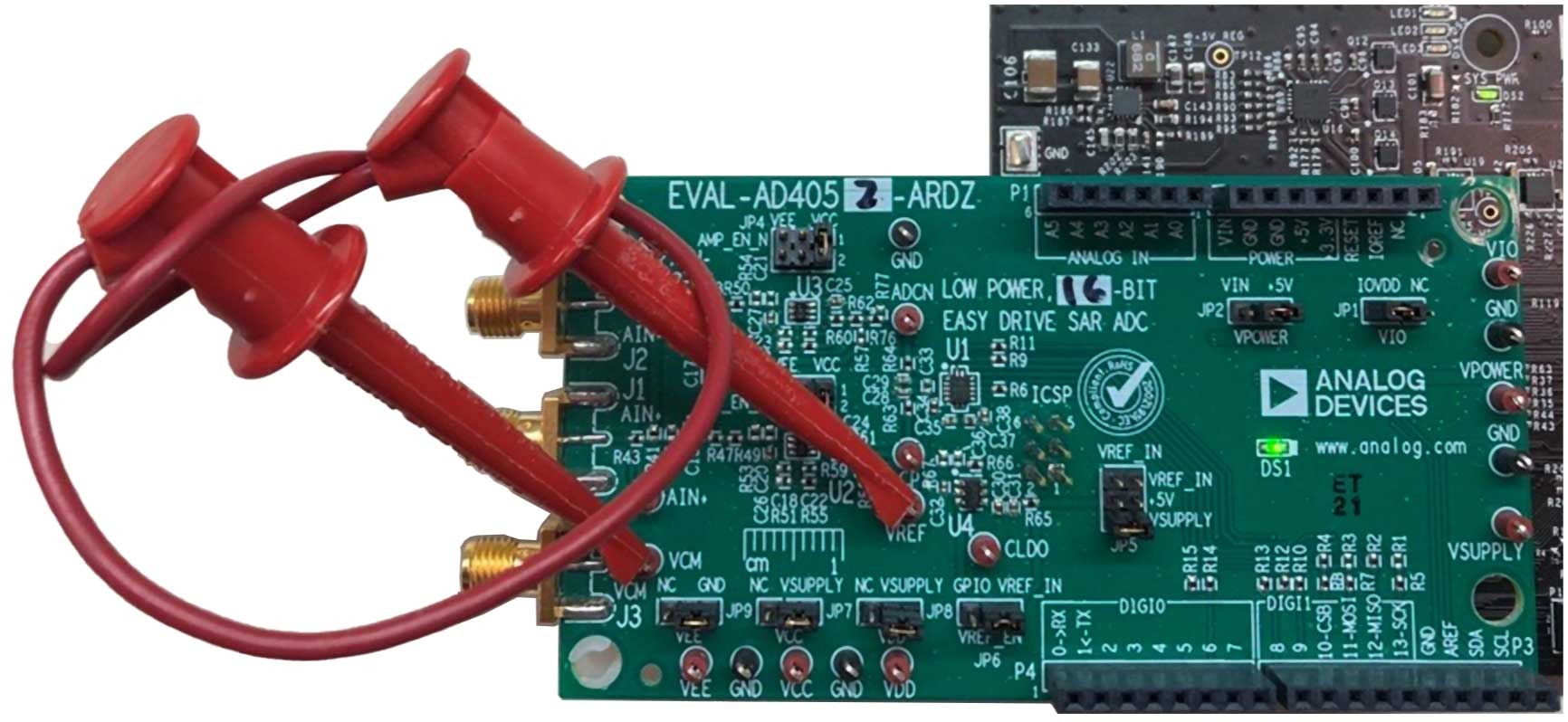
Figure 1 Biasing the EVAL-AD4052-ARDZ Inputs Without Signal Generator Hardware for Software Validation
IIf no signal generator is available, a jumper cable between the VREF and VCM test points can be used to bias the AD4050/ AD4052 analog inputs to VREF. This is preferred over connecting the amplifier inputs to GND, because the amplifier VEE rails are connected to GND by default.
Evaluation board hardware
Follow UG-2222, Evaluation Board Hardware section.
Evaluation board software
For no-OS basic examples, the evaluation board is interfaced through any serial
software such as minicom, picocom and putty (see TODO :external+no-OS:doc:`projects/ad405x`,
Basic Example section).
Using no-OS tinyIIO example, precision-converters-firmare or Linux, the interface is done through Libiio
For no-OS tinyIIO and precision-converters-firmware, execute on the host PC:
~$
iio_info -u serial:/dev/ttyACM0,115200,8n1
And for Linux, on the carrier Linux shell:
~$
iio_info
Or from the host, with a Ethernet cable connected to the carrier:
~$
iio_info -u ip:192.168.2.1
(the IP address depends on your local network and carrier settings).
You can also use IIO Oscilloscope on to obtain waveforms using a GUI.