Hardware User Guide
Overview
The EVAL-ISOMAX is an integrated dual isoSPI adapter and microcontroller board featuring the MAX32670 high-reliability, ultralow power microcontroller and the ADBMS6822 dual isoSPI transceiver. This board allows multiple ADBMS68xx battery monitors to be connected through daisy chain configuration.
The EVAL-ISOMAX also features reversible isoSPI, which enables a redundant path to the peripheral units. The PCB components and DuraClik connectors are optimized for low electromagnetic interference (EMI) susceptibility and emissions.
Hardware Setup when using EVAL-ISOMAX as a Standalone MCU with Other BMS Boards
This section describes the procedure for establishing hardware connection between the EVAL-ISOMAX and other ADI Broad Market BMS boards, how to download the software files such as the firmware and GUI installer, and eventually obtain and view BMS readings through the BMS graphical user interface.
Before you proceed with the system setup, make sure you have the following:
Equipment Needed
Boards
1x EVAL-ISOMAX Dual isoSPI Adapter and Microcontroller Board
2x EVAL-ADBMS6830BMSW 16-Channel Battery Cell Monitor
1x EVAL-ADBMS2950-BASIC Battery Pack Monitor
2x DC2472A Battery Cell Emulator
1x MAX32625PICO Programming Adapter with 10-pin SWD cable
Cables and Other Equipment
2x Cell Connector Block (18-cell connector)
3x DuraClik isoSPI Twisted Pair Cables
3x USB Type A to Micro-B Cable
Laptop or PC running Windows 10
Digital power supply (such as the Keysight e3631A 0V to 6V power supply)
2x wall plugs (to plug USB cable from DC2472A to provide power)
Software Needed
The BMS Broadmarket Browser GUI is a PC browser-based graphical user interface (GUI) tool designed to work in conjunction with the ADI Broad Market BMS devices.
MyAnalog.com account is required in downloading the BMS Browser GUI from BMS Browser GUI Version 2.0.0
When software updates or new versions of the software are available, an email notification will be sent to the email address associated with the MyAnalog account used to download the original software package.
Programming the MCU using the MAX32625PICO Adapter
This procedure is required to be done before connecting other BMS boards to the EVAL-ISOMAX.
Make sure that you have downloaded and installed the BMS Browser GUI to the host PC before programming the MCU.
Follow these steps if the EVAL-ISOMAX is used as a standalone MCU:
Download the firmware image: MAX32625PICO Firmware Image for MAX32670 MCU
Connect the MAX32625PICO to the Host PC using the microUSB to USB cable.
Press the button on the MAX32625PICO. (Do not release the button until the MAINTENANCE drive is mounted).
Release the button once the MAINTENANCE drive is mounted.
Drag and drop the firmware image into the MAINTENANCE drive.
After a few seconds, the MAINTENANCE drive will disappear and be replaced by a drive named DAPLINK. This indicates that the process is complete, and the MAX32625PICO can now be used to flash the firmware.
Connect the MAX32625PICO to the EVAL-ISOMAX using the 10-pin SWD ribbon cable.
Connect the EVAL-ISOMAX to the Host PC using a USB cable.
A DAPLINK drive should appear in Windows Explorer.
Uploading the EVAL-ISOMAX Firmware into the Broadmarket BMS Browser GUI Installer
Download and extract the EVAL-ISOMAX folder in the host PC.
Copy and paste the entire EVAL-ISOMAX folder into the USB_TO_SPI directory inside the Broadmarket BMS GUI installation folder.
Location: C:\Analog Devices\BMS_Browser_GUI_Broadmarket-Rel2.0.0\USB_TO_SPI_Firmware
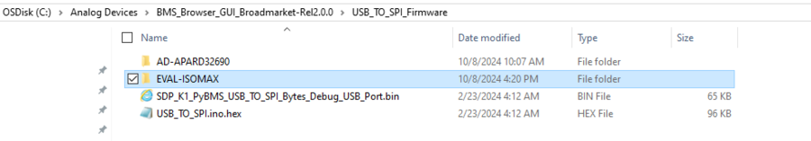
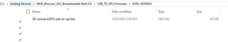
Make sure that the copied folder contains the isomax32670-usb-to-spi.hex file.
The EVAL-ISOMAX board is now ready to be used with the Broadmarket BMS Browser GUI. Refer to the next sections for procedure on how to set up the hardware for evaluation.
Battery Cell Monitoring (EVAL-ISOMAX + EVAL-ADBMS6830BMSW)
Hardware Connection
The DC2472A Battery Emulator Board is used for cell voltage input in this setup. Alternatively, resistors can be used to simulate battery cell voltages. 100 Ω ½ W or equivalent resistors are recommended because 100 Ω (or lower values) typically will not induce measurement errors, and the ½ W (or greater rating) will keep the resistor temperatures low, preventing power dissipation damage.
Check the EVAL-ADBMS6830BMSW User Guide for procedure on connecting resistors.
Plug the screw-terminal block into the cell voltage connector of the DC2472A battery emulator board. Note that the last three terminals of the DC2472A must be left hanging.
Connect the DC2472A battery emulator board to the EVAL-ADBMS6830BMSW through the connected cell voltage connectors (J1).
Connect a 5 V external power source to the DC2472A (J1) using a USB cable. Alternatively, power it through PC using a USB cable to be connected via J10.
While some laptop USB ports may suffice for powering the emulator during evaluation, it is still recommended to use an external power supply to ensure adequate power. Note that the EVAL-ADBMS6830BMSW is powered through the DC2472A.
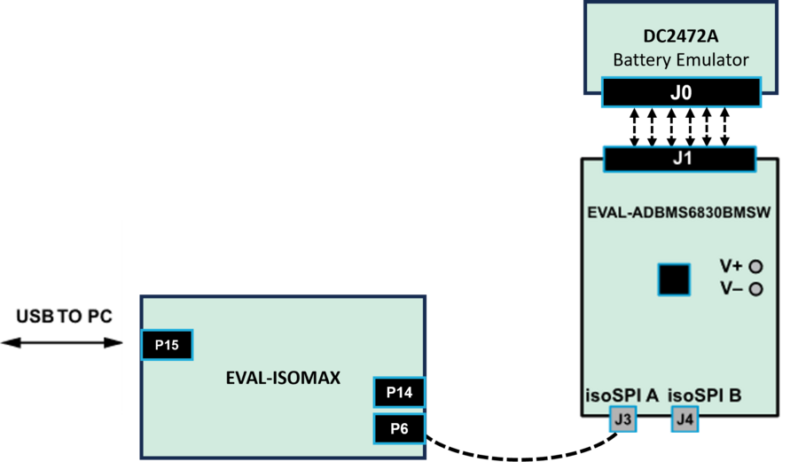
Connect the EVAL-ISOMAX (P6) to the EVAL-ADBMS6830BMSW (J3) using the 2-wire twisted-pair patch cable from the main DuraClik connector to isoSPI A DuraClik connector.
Plug the micro-USB to USB cable into P15 of the EVAL-ISOMAX. Connect the other end to a PC/Laptop. DS3 (Green), DS2 (Red), and DS5 (Red) LEDs should light up indicating a default power up.
Connect the 10-pin SWD debugger cable to port P12 of the EVAL-ISOMAX. Connect the other end of the SWD debugger cable to the MAX32625PICO. Observe correct polarity when connecting the SWD cable.
Use the micro-USB to USB cable to connect the MAX32625PICO to the PC/Laptop.
Testing the Setup
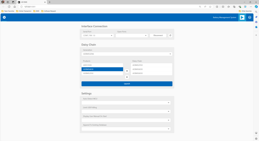
Open the BMS Browser GUI.
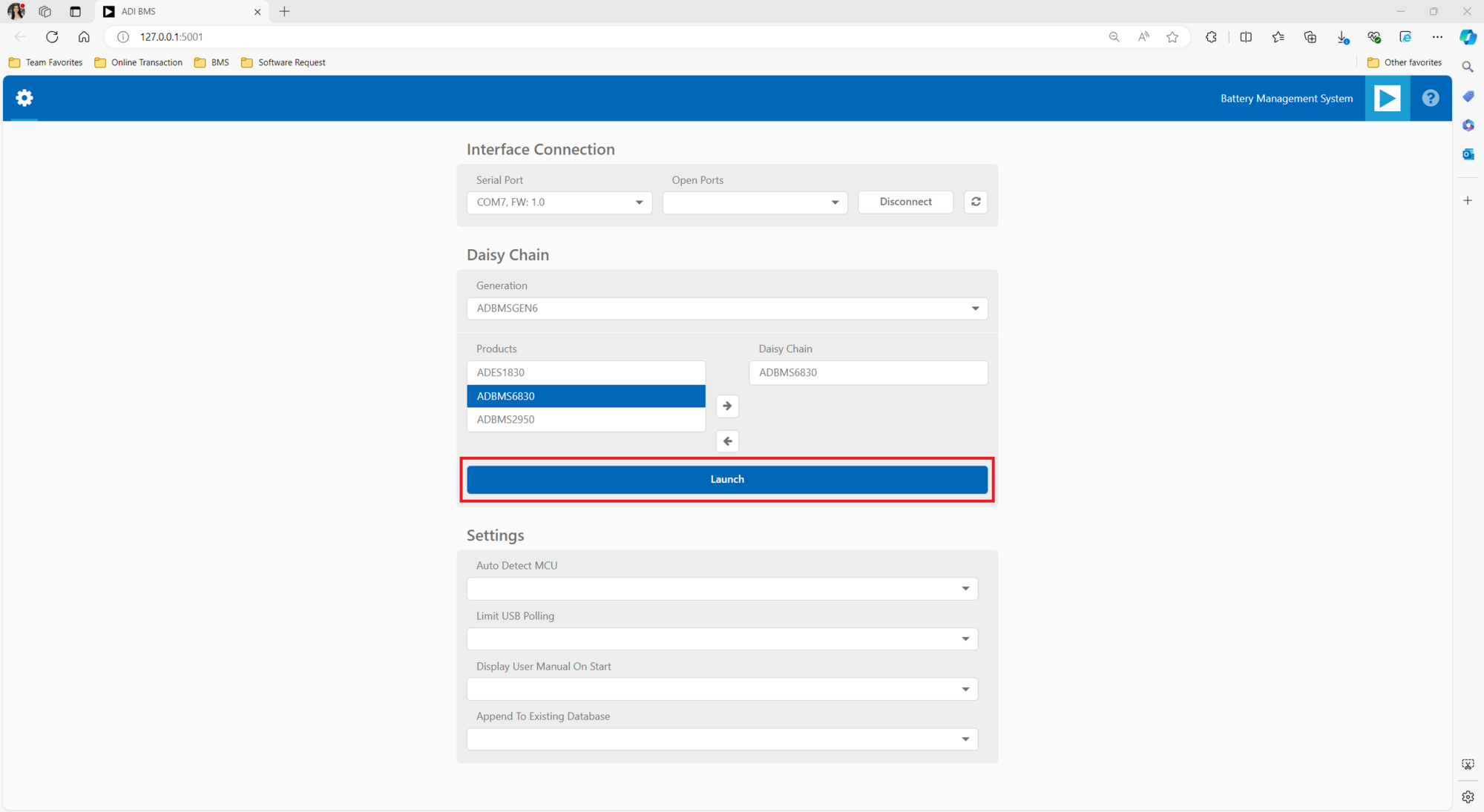
In the Interface Connection section, select the COM port associated with the EVAL-ISOMAX.
Under the Daisy Chain section, ensure that the Generation drop down box is set to ADBMSGEN6.
From the Products list, select the ADBMS6830, then click on the right arrow to add it to the Daisy Chain. Other Settings can remain as default.
Click Launch.
Upon launching, the Quick Measure tab will open. Note: this utility only supports a single BMS product in a daisy chain. Click Start Quick Measure to begin measurements.
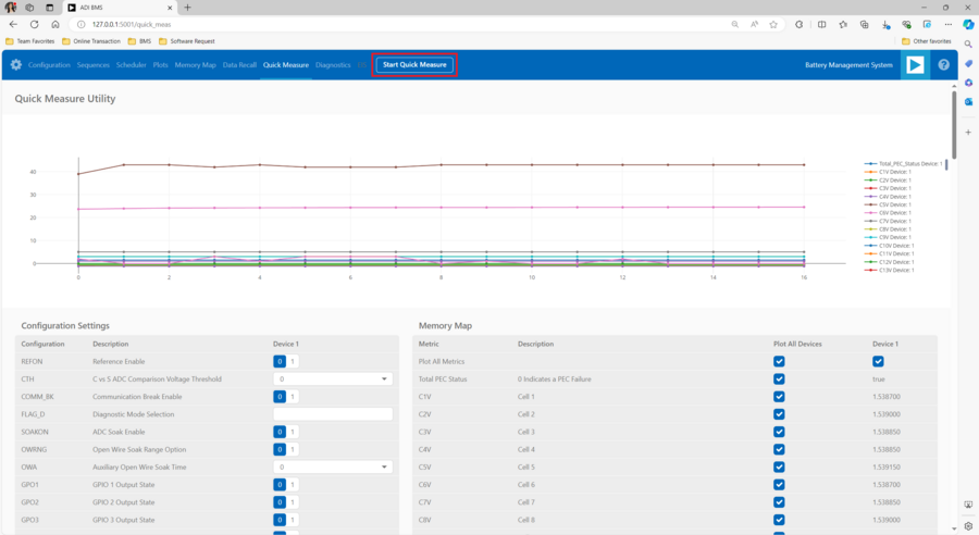
Check the Total PEC Status on the 3rd row under the Memory Map. This indicates the status of the isoSPI link between the EVAL-ISOMAX and the EVAL-ADBMS6830BMSW.
Ensure the EVAL-ADBMS6830BMSW board is powered correctly, indicated by the Blue LED on the DC2472A emulator board being illuminated.
Verify the connection of the twisted cable between the EVAL-ISOMAX and the EVAL-ADBMS6830BMSW.
Check the voltage readings by adjusting the potentiometer (POT1) on the DC2472A to modify the emulated cell voltages.
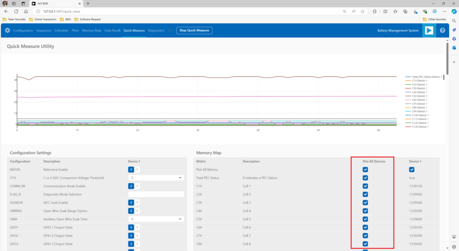
Monitor the voltage channels on the Quick Measure Utility graph.
Select which signals to display on the graph under the Plot All Devices column.
Battery Pack Monitoring (EVAL-ISOMAX + EVAL-ADBMS2950-BASIC)
Hardware Connection
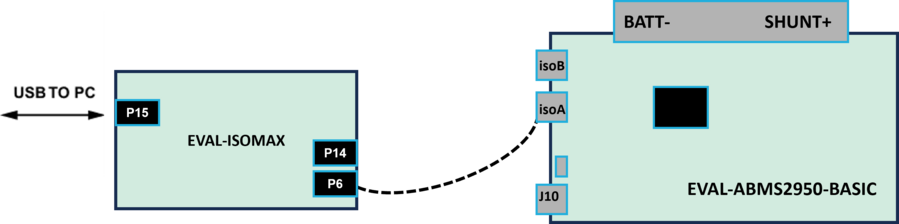
Connect the EVAL-ISOMAX (P6) to the EVAL-ADBMS2950-BASIC (isoA) using the provided twisted-pair DuraClik cable
Choose between two options for powering the EVAL-ADBMS2950-BASIC:
Using an external power source, supply 5 V (via J1) and set the current limit to 200 mA. The EVAL-ADBMS2950-BASIC consumes <50 mA in idle mode and ~100 mA in active mode.
Alternatively, power the board using a micro-USB cable connected to J10.
Attach the MAX32625PICO programmer to the EVAL-ISOMAX using the 10-pin ribbon SWD cable. Observe correct polarity when connecting the SWD cable.
Connect one end of the USB cable to EVAL-ISOMAX (P15) and the other end to the host PC.
Testing the Setup
Open the BMS Browser GUI.
Go to the Interface Connection section and select the COM port associated with the EVAL-ISOMAX.
Under the Daisy Chain section, ensure the Generation drop-down box is set to ADBMSGEN6.
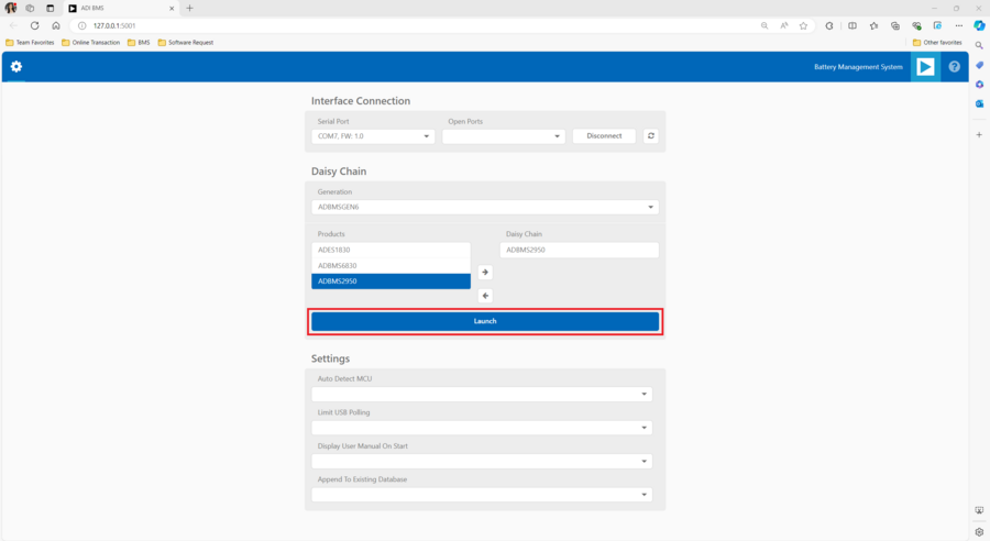
From the Products list, select the ADBMS2950, then click on the right arrow to add it to the Daisy Chain. Settings can remain as default.
Click Launch.
Upon launching, the Quick Measure tab will open. Note: it can only handle one BMS product in a Daisy Chain. Click Start Quick Measure to begin measurements.
Check the Total PEC Status on the Memory Map. It should reflect true, indicating a successful isoSPI link between the EVAL-ISOMAX and the EVAL-ADBMS2950-BASIC. If false, there is an error in the signal chain.
Complete Daisy Chain
Once familiar with the setup for each of the individual boards the entire signal chain can be verified.
Hardware Connection
Connect the hardware using the DuraClik isoSPI cables, as shown in the diagram below.
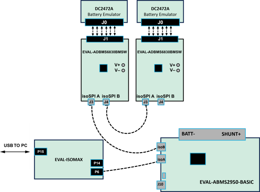
Power each DC2472A using a 5V external source connected to J1 through the USB cable.
Power the EVAL-ADBMS2950-BASIC either through J1 or J10, as explained earlier.
Using the black alligator clip cable, connect the V- pin of the second EVAL-ABMS6830BMSW to the BATT- port of the EVAL-ADBMS2950-BASIC.
Using the red alligator clip cable, connect the V- pin of the first EVAL-ABMS6830BMSW board to the V+ pin of the second EVAL-ADBMS6830BMSW.
Attach the MAX32625PICO programmer to the EVAL-ISOMAX using the 10-pin ribbon SWD cable. Observe correct polarity when connecting the SWD cable.
Connect one end of the USB cable to EVAL-ISOMAX (P2) and the other end to the host PC.
Testing the Setup
Launch the BMS Browser GUI following the previous instructions and choose the appropriate COM port associated to the EVAL-ISOMAX.
Set up the Daisy Chain according to the diagram provided. The EVAL-ADBMS2950-BASIC is positioned at the top, indicating it is the initial device on the chain. The first EVAL-ADBMS6830BMSW connects to the EVAL-ADBMS2950-BASIC, while the second EVAL-ADBMS6830BMSW is linked to the first one via the isoSPI cable.
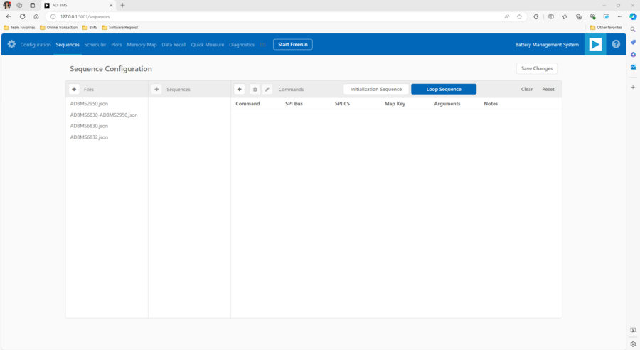
Click on the Launch button to initiate the GUI. After the GUI launches in the browser, go to the Sequences tab located in the top toolbar, this will open the Sequence Configuration page.
Under Files, select ADBMS6830-ADBMS2950.json. This action will load a preconfigured sequence into the tool.
Click on Initialization Sequence followed by General Initialization under the Sequences column to load the defined sequences from the ADBMS6830-ADBMS2950.json file into the tool.
Next, select Loop Sequence and then click on General Readback Loop under the Sequences column. This action loads the loop sequence defined in the ADBMS6830-ADBMS2950.json file into the tool.
Finally, click on Start Freerun to initiate the freerun mode.
During free run mode, the Initialization Sequence is performed once initially. Subsequently, the loop sequence continues to run continuously until the Stop Freerun button is clicked.
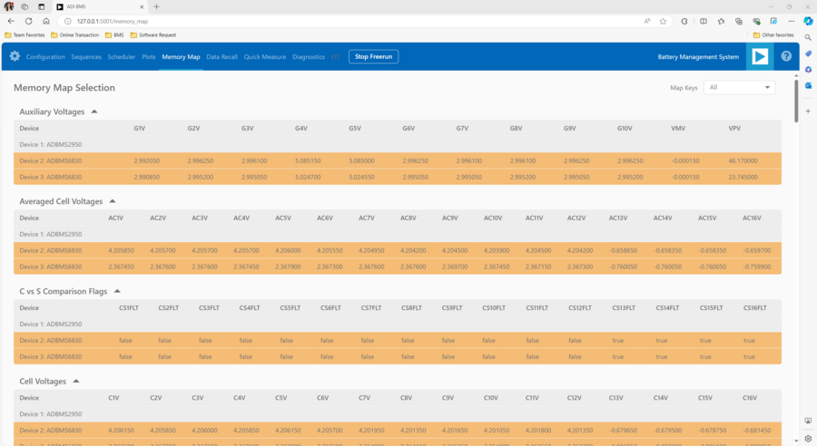
After activating freerun mode, navigate to the Memory Map tab. This section displays a numerical representation of the ongoing command loop. Additional details can be accessed in the GUI’s help section. The accompanying screenshot illustrates this output.
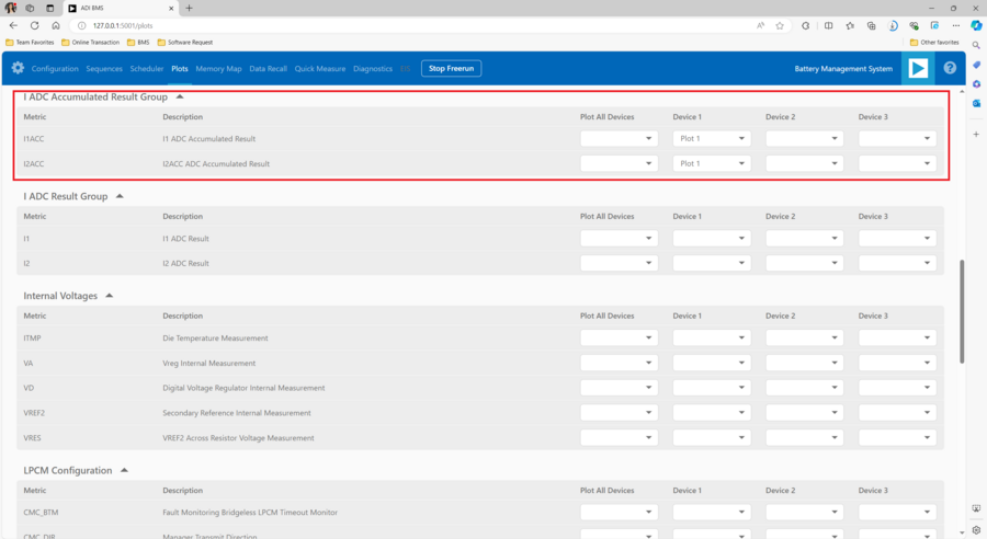
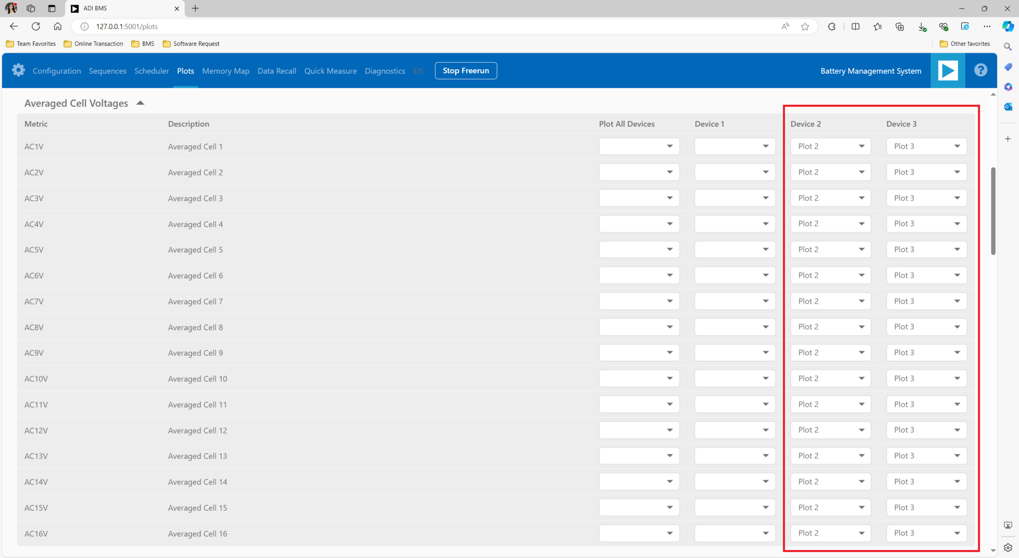
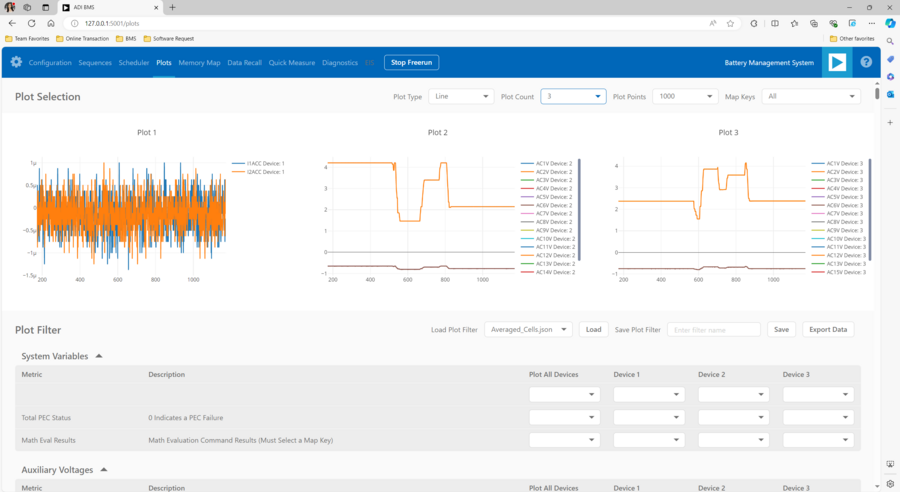
The Plots tab allows for the visualization of parameters recorded during the command loop. It supports the creation of up to four plots simultaneously. In the configured Daisy Chain, the EVAL-ADBMS2950-BASIC is designated as Device 1, the first EVAL-ADBMS6830BMSW as Device 2, and the third EVAL-ADBMS6830BMSW as Device 3. An example illustrates how to plot each parameter separately: I1ACC and I2ACC on Plot 1, the average cell voltages for the first EVAL-ADBMS6830MSW on Plot 2, and the averaged cell voltages for the third EVAL-ADBMS6830BMSW on Plot 3.
Simply choose the desired Plot number from the dropdown menu under each device to display the relevant data.
Plot settings can be saved to the PC to be reloaded for future session to save time.
Hardware Setup when using EVAL-ISOMAX as a Secondary Device to Other MCU Boards
This section describes how to configure EVAL-ISOMAX as a secondary device to another MCU board such as the AD-APARD32690-SL and SDP-K1 and use it with other ADI Broad Market BMS board for evaluation.
Before you proceed with the system setup, make sure you have the following:
Equipment Needed
Boards
1x Microcontroller Board (such as the AD-APARD32690-SL or SDP-K1)
1x EVAL-ISOMAX Dual isoSPI Adapter and Microcontroller Board
2x EVAL-ADBMS6830BMSW 16-Channel Battery Cell Monitor
1x EVAL-ADBMS2950-BASIC Battery Pack Monitor
2x DC2472A Battery Cell Emulator
1x MAX32625PICO Programming Adapter with 10-pin SWD cable
Cables and Other Equipment
2x Cell Connector Block (18-cell connector)
3x DuraClik isoSPI Twisted Pair Cables
3x USB Type A to Micro-B Cable
Laptop or PC running Windows 10
Digital power supply (such as the Keysight e3631A 0V to 6V power supply)
2x wall plugs (to plug USB cable from DC2472A to provide power)
Software Needed
The BMS Browser is a PC browser based Graphical User Interface (GUI) tool designed to work in conjunction with the Broad Market BMS devices.
MyAnalog.com account is required in downloading the BMS Browser GUI from below link:
When software updates or new versions of the software are available an email notification will be sent to the email address associated with the MyAnalog account used to download the original software package.
MCU Configuration
This procedure is required to be done before connecting other BMS boards to the EVAL-ISOMAX.
Make sure that you have downloaded and installed the BMS Browser GUI to the host PC before programming the MCU.
Follow these instructions if AD-APARD32690-SL is used as the main controller board:
Download the firmware image: MAX32625PICO Firmware Image for MAX32690 MCU
Connect the MAX32625PICO to the Host PC using the microUSB to USB cable.
Press the button on the MAX32625PICO. (Do not release the button until the MAINTENANCE drive is mounted)
Release the button once the MAINTENANCE drive is mounted.
Drag and drop the firmware image to the MAINTENANCE drive.
After a few seconds, the MAINTENANCE drive will disappear and be replaced by a drive named DAPLINK. This indicates that the process is complete, and the MAX32625PICO can now be used to flash the firmware.
Connect the MAX32625PICO to the AD-APARD32690-SL using the 10-pin SWD ribbon cable.
Connect the AD-APARD32690-SL to the Host PC using a USB cable.
A DAPLINK drive should appear in Windows Explorer.
Locate the firmware HEX file to be programmed on the MCU board in the installation folder of the BMS Browser GUI Broadmarket. Location: C:\AnalogDevices\BMS_Browser_GUI_Broadmarket-Rel2.0.0\USB_TO_SPI_Firmware
Drag and drop the usb-to-spi-max32690.hex file to the DAPLINK drive to flash the firmware needed by the BMS Browser GUI.
A normal copy progress dialog will appear. Once the progress bar is completed, the dialog window will close, and the DAPLINK drive will reconnect.
Check the DAPLINK directory and make sure there is no FAIL.TXT file. In case there is, repeat the drag and drop step. Otherwise, the MAX32625PICO can now be disconnected from the AD-APARD32690-SL, since the firmware update is complete.
Follow these steps if SDP-K1 is used as the main controller board:
Connect the SDP-K1 microcontroller board to the host PC using a USB cable.
Locate the firmware .hex file to be programmed on the MCU board in the installation folder of the BMS Browser GUI Broadmarket. Location: C:\Analog Devices\BMS_Browser_GUI_Broadmarket-Rel2.0.0\USB_TO_SPI_Firmware
Drag and drop the SDP_K1_PyBMS_USB_TO_SPI_Bytes_Debug_USB_Port.hex file onto the corresponding SDP-K1 drive to update the firmware.
Battery Cell Monitoring
Hardware Connection
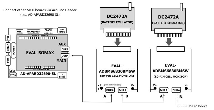
Figure 16 Cell Monitoring Setup using the EVAL-ISOMAX as isoSPI with a Different MCU as Host Controller
The DC2472A Battery Emulator Board is used for cell voltage input in this setup. Alternatively, resistors can be used to simulate battery cell voltages. 100 Ω ½ W or equivalent resistors are recommended because 100 Ω (or lower values) typically will not induce measurement errors, and the ½ W (or greater rating) will keep the resistor temperatures low, preventing power dissipation damage.
Check the EVAL-ADBMS6830BMSW User Guide for procedure on connecting resistors.
Battery Emulator Board Setup:
Use the DC2472A Battery Emulator Board for cell voltage input.
Alternatively, use 100 Ω ½ W resistors to simulate battery cell voltages. Refer to the EVAL-ADBMS6830BMSW User Guide for resistor connection procedures.
Connecting the Emulator Board:
Plug the screw-terminal block into the cell voltage connector of the DC2472A.
Leave the last three terminals of the DC2472A hanging.
Connect the DC2472A to the EVAL-ADBMS6830BMSW via the cell voltage connectors (J1).
Powering the Emulator Board:
Connect a 5V external power source to the DC2472A (J1) using a USB cable. External power supply is recommended for adequate power.
Alternatively, power it through a PC using a USB cable connected via J10.
Connecting the EVAL-ISOMAX:
Attach the EVAL-ISOMAX to the AD-APARD32690-SL (or SDP-K1) through the Arduino Headers.
Connect the EVAL-ISOMAX (P6) to the EVAL-ADBMS6830BMSW (J3) using a 2-wire twisted-pair patch cable.
Configuring Jumpers:
On the EVAL-ISOMAX, set Jumpers P16, P17, and P18 to position 2 and 3 to use power from the main MCU.
Connecting to PC:
Plug the micro-USB to USB cable into the AD-APARD32690-SL (or SDP-K1).
Connect the other end to a PC/Laptop.
Ensure DS3 (Green), DS2 (Red), and DS5 (Red) LEDs light up, indicating a default power up.
Connecting the Debugger:
Connect the 10-pin SWD debugger cable to the AD-APARD32690-SL (or SDP-K1).
Connect the other end of the SWD debugger to the MAX32625PICO.
Testing the Setup
Open the BMS Browser GUI.
Select the COM Port:
In the Interface Connection section, choose the COM port associated with the AD-APARD32690-SL (or SDP-K1).
Configure Daisy Chain:
Set the Generation drop-down box to ADBMSGEN6.
From the Products list, select ADBMS6830 and add it to the Daisy Chain.
Launch the GUI:
Click Launch.
The Quick Measure tab will open. Note: This utility supports only a single BMS product in a Daisy Chain.
Click Start Quick Measure to begin measurements.
Check Connections and Status:
Verify the Total PEC Status on the 3rd row under the Memory Map to checkthe isoSPI link status between the EVAL-ISOMAX and the EVAL-ADBMS6830BMSW.
Ensure the EVAL-ADBMS6830BMSW board is powered correctly (Blue LED on the DC2472A should be illuminated).
Verify the connection of the twisted cable between the EVAL-ISOMAX and the EVAL-ADBMS6830BMSW.
Adjust and Monitor Voltages:
Adjust the potentiometer (POT1) on the DC2472A to modify the emulated cell voltages.
Monitor the voltage channels on the Quick Measure Utility graph.
Select which signals to display on the graph under the Plot All Devices column.
Battery Pack Monitoring
Hardware Connection
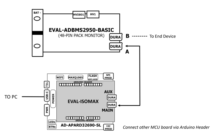
Figure 17 Pack Monitoring Setup using the EVAL-ISOMAX as isoSPI with a Different MCU as Host Controller
Attach EVAL-ISOMAX:
Connect the EVAL-ISOMAX to the AD-APARD32690-SL (or SDP-K1) through the Arduino Headers.
Set Jumpers P16, P17, and P18 on the EVAL-ISOMAX to position 2 and 3 to use power from the main MCU.
Connect to EVAL-ADBMS2950-BASIC:
Use the provided isoSPI cable to connect EVAL-ISOMAX (P6) to EVAL-ADBMS2950-BASIC (isoA).
Powering EVAL-ADBMS2950-BASIC:
Option 1: Supply 5 V to J1 and set the current limit to 200 mA (consumes less than 50 mA in idle mode and ~100 mA in active mode).
Option 2: Use a micro-USB cable connected to J10.
Attach MAX32625PICO:
Connect the MAX32625PICO to the AD-APARD32690-SL (or SDP-K1) using the 10-pin ribbon SWD cable, ensuring correct polarity.
Connect to PC:
Use a USB cable to connect the AD-APARD32690-SL (or SDP-K1) to the host PC.
Testing the Setup
Open the BMS Browser GUI.
Select the COM Port:
In the Interface Connection section, choose the COM port associated with the AD-APARD32690-SL (or SDP-K1).
Configure Daisy Chain:
Set the Generation dropdown box to ADBMSGEN6.
From the Products list, select ADBMS2950 and add it to the Daisy Chain.
Launch the GUI:
Click Launch.
The Quick Measure tab will open. Note: This utility supports only a single BMS product in a Daisy Chain.
Click Start Quick Measure to begin measurements.
Check Connections and Status:
Verify the Total PEC Status on the Memory Map. It should reflect true, indicating a successful isoSPI link between the EVAL-ISOMAX and the EVAL-ADBMS2950-BASIC. If it shows false, there is an error in the signal chain.
Complete Daisy Chain
Once familiar with the setup for each of the individual boards the entire signal chain can be verified.
Hardware Connection
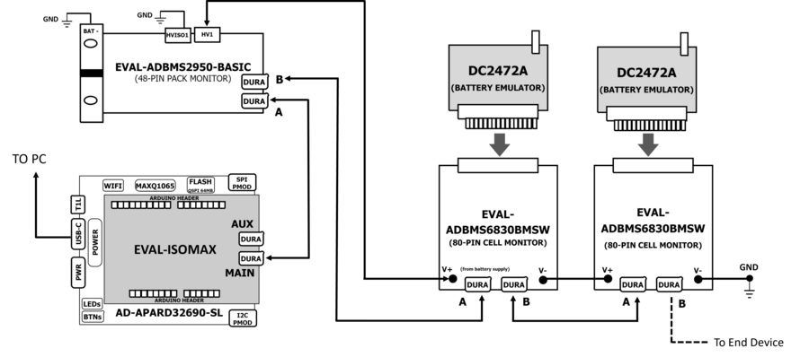
Figure 18 Daisy Chain Setup using the EVAL-ISOMAX as isoSPI with a Different MCU as Host Controller
Connect the hardware using the DuraClik isoSPI cables.
Power each DC2472A using a 5 V external source connected to J1 through the USB cable.
Power the EVAL-ADBMS2950-BASIC either through J1 or J10, as explained earlier.
Using the black alligator clip cable, connect the V- pin of the second EVAL-ABMS6830BMSW to the BATT- port of the EVAL-ADBMS2950-BASIC.
Using the red alligator clip cable, connect the V- pin of the first EVAL-ABMS6830BMSW board to the V+ pin of the second EVAL-ADBMS6830BMSW.
Attach the MAX32625PICO to the AD-APARD32690-SL (or SDP-K1 if this is used) using the 10-pin ribbon SWD cable. Observe correct polarity when connecting the SWD cable.
Connect a USB cable to the AD-APARD32690-SL (or SDP-K1 if this is used) and the other end of the cable to the host PC.
Testing the Setup
Launch the BMS Browser GUI following the previous instructions.
Choose the appropriate COM port associated to the AD-APARD32690-SL or SDP-K1 controller board.
Set up the Daisy Chain according to the diagram provided. The EVAL-ADBMS2950-BASIC is positioned at the top, indicating it is the initial device on the chain. The first EVAL-ADBMS6830BMSW connects to the EVAL-ADBMS2950-BASIC, while the second EVAL-ADBMS6830BMSW is linked to the first one via the isoSPI cable.
Click on Launch to initiate the GUI. After the GUI launches in the Browser, go to the Sequences tab located in the top toolbar, which will open the Sequence Configuration page.
In the Files column, select ADBMS6830-ADBMS2950.json. This action will load a preconfigured sequence into the tool.
Click on Initialization Sequence followed by General Initialization under the Sequences column to load the defined sequences from the ADBMS6830-ADBMS2950.json file into the tool.
Next, select Loop Sequence and then click on General Readback Loop under the Sequences column. This action loads the loop sequence defined in the ADBMS6830-ADBMS2950.json file into the tool.
Finally, click on Start Freerun to initiate the freerun mode.
During free run mode, the Initialization Sequence is performed once initially. Subsequently, the loop sequence continues to run continuously until the Stop Freerun button is clicked.
After activating freerun mode, navigate to the Memory Map tab. This section displays a numerical representation of the ongoing command loop. Additional details can be accessed in the GUI’s help section. The accompanying screenshot illustrates this output.
The Plots tab allows for the visualization of parameters recorded during the command loop. It supports the creation of up to four plots simultaneously. In the configured Daisy Chain, the EVAL-ADBMS2950-BASIC is designated as Device 1, the first EVAL-ADBMS6830BMSW as Device 2, and the third EVAL-ADBMS6830BMSW as Device 3. An example illustrates how to plot each parameter separately: I1ACC and I2ACC on Plot 1, the average cell voltages for the first EVAL-ADBMS6830BMSW on Plot 2, and the averaged cell voltages for the third EVAL-ADBMS6830BMSW on Plot 3.
Simply choose the desired Plot number from the dropdown menu under each device to display the relevant data.
Plot settings can be saved to the PC to be reloaded for future session to save time.
Design and Integration Files
Help and Support
For questions and more information about this product, connect with us through the Analog Devices EngineerZone.