Introduction to Electronics
Note
This is a work in progress.
Introduction
This workshop is designed for freshmen and second-year students who are passionate about electronics and electrical engineering. It aims to provide them with a comprehensive overview of the field.
The content and structure are tailored to their current level of knowledge, introducing them to the fascinating world of electronics and microchips.
Theoretical content
Why choosing Electronics
What is an IC and what role does it have
What is a transistor and what role does it have
ADALM2000 board overview
Why Electronics?
Every Electronics or Electrical Engineering student has received at least once the question: why did you choose electronics? How can one answer this question better than: Why not?
It offers diverse career opportunities:
Wireless Communications Engineer
Network Engineer
Electronics Design Engineer
Embedded Systems Engineer
Satellite Communications Engineer
It brings to table inovation and technological advancement
It offers impactful contribution
It offers continuous learning
What is an IC?
An integrated circuit (IC) is an assembly of electronic components in which hundreds to millions of transistors, resistors, and capacitors are interconnected and built up on a thin substrate of semiconductor material (usually silicon) to form a small chip or wafer. Integrated circuits are the building blocks for most electronic devices and equipment.
Applications
Consumer Electronics: Smartphones, computers, and home appliances.
Industrial: Automation systems, robotics.
Medical: Diagnostic equipment, wearable health devices.
Automotive: Engine control units, infotainment systems.
Importance
Miniaturization of circuits.
Increased reliability and performance.
Cost efficiency.
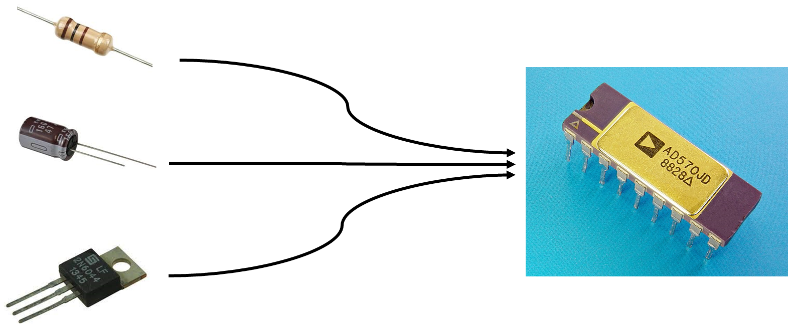

Figure 2 LSI – Large Scale Integration circuits compared to the corresponding prototype circuit 1970-1972
Transistors - what kind of species is that?
A transistor is a miniature semiconductor that regulates or controls current or voltage flow in addition amplifying and generating these electrical signals and acting as a switch/gate for them
why do we need them?
how do they work?
what are the commonly used types?
Applications
Analog Circuits: Amplifiers, oscillators.
Digital Circuits: Logic gates, microprocessors.
Power Electronics: Power supplies, motor controllers.
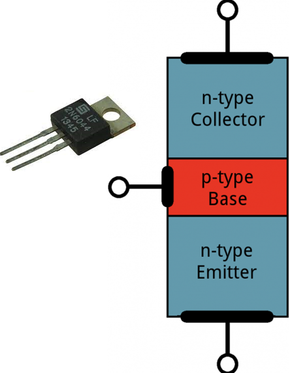
Functionality
Cut Off (“off”): Emitter > Base < Collector
Saturation (“on”): Emitter < Base > Collector
Forward Active (“proportional”): Emitter < Base < Collector
Reverse Active (“negative proportional”): Emitter > Base > Collector
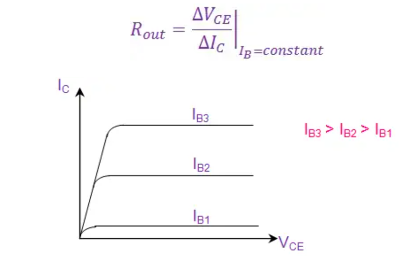
Figure 4 Output Characteristics - common emitter configuration
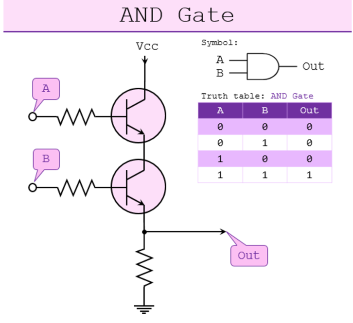
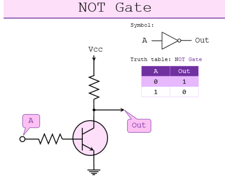
How many transistors are needed to create a logic gate?
Logic gates built with transistors
ADALM2000
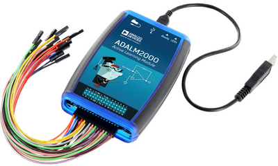
The ADALM2000 (M2K) Advanced Active Learning Module is an affordable USB-powered data acquisition module, that can be used to introduce fundamentals of electrical engineering in a self or instructor lead setting.
With 12-bit ADCs and DACs running at 100 MSPS, brings the power of high-performance lab equipment to the palm of your hand, enabling electrical engineering students and hobbyists to explore signals and systems into the tens of MHz without the cost and bulk associated with traditional lab gear.
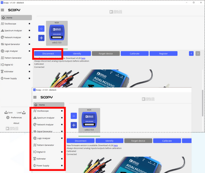
When coupled with Analog Devices’ Scopy™ graphical application software running on a computer, provides the user with high performance instrumentation.
Hands-on activity
By the end of this workshop, you will learn:
How to use a breadboard
How to power on an IC
How to read an IC pinout from datasheet
How to use a desktop Oscilloscope and Signal generator channels by operating a Network Analyzer
How to visualize a low pass filter characteristic / transfer function
How to drive a transistor
How to create a logic function for performing a specific task
Activities
Low pass filter transfer function
Digital demo – traffic lights using logic gates
Back to the analog world - Transistors
Home made battery
Pre-requisites
Hands-on activity 1 - Scope and Signal generator channels – Cascaded LP filters
Materials
ADALM2000 Active Learning Module
Solder-less breadboard, and jumper wire kit
2 x 1 KΩ resistors
2 x 0.1 uF capacitors (marked 104)
First Stage Filter
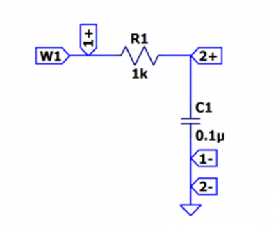
Hardware setup
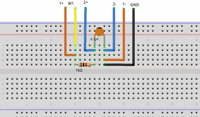
Steps
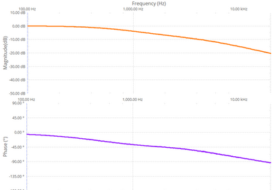
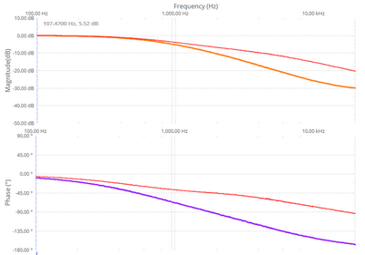
Open Network Analyzer
Set the sweep to logarithmic
Set the start frequency to 100Hz and stop to 20kHz
Set the magnitude axis between -50dB and 10dB
Set the phase axis between -180 and 90 degrees
Second stage filter
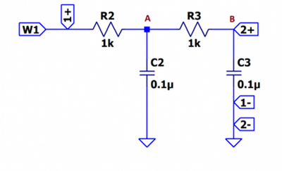
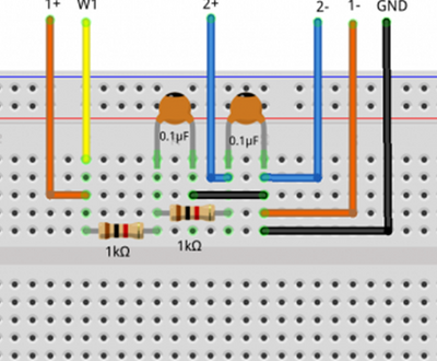
Steps:
Connect the Scope Channel 2 after the first RC group and do a single sweep
Take a signal snapshot to preserve the result as a reference
Connect the Scope Channel 2 after the second RC stage and perform another sweep
Hands-on activity 2 - Traffic lights control
This demo will showcase the usage of logic gates to implement a logic function which describes the functionality of a well-known device: a traffic light.
Materials
ADALM2000 Active Learning Module
Jumper wires
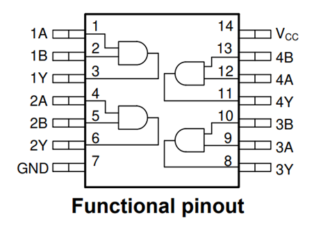
1 SN74HC08N part
1 SN74HC32N part
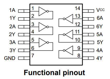
1 SN74HC04N part
1 Yellow LED
1 Red LED
1 Green LED
Theory of operation
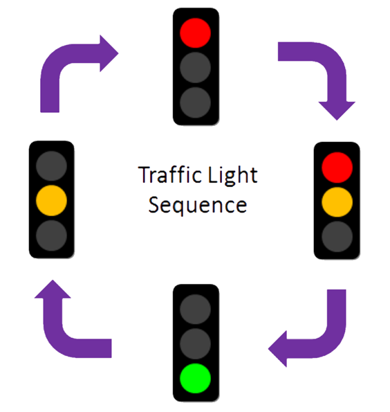
Logic sequence of a traffic light is the one bellow:
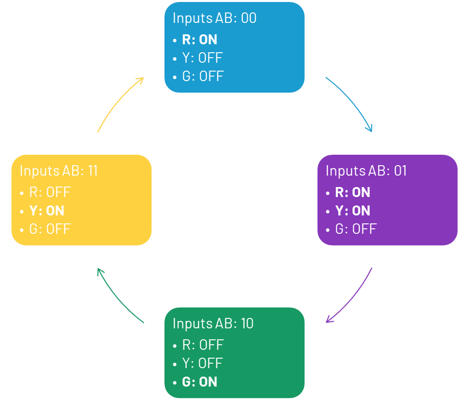
You will use two logic inputs to control the traffic lights, those inputs are marked A and B, the sequence is the one bellow:
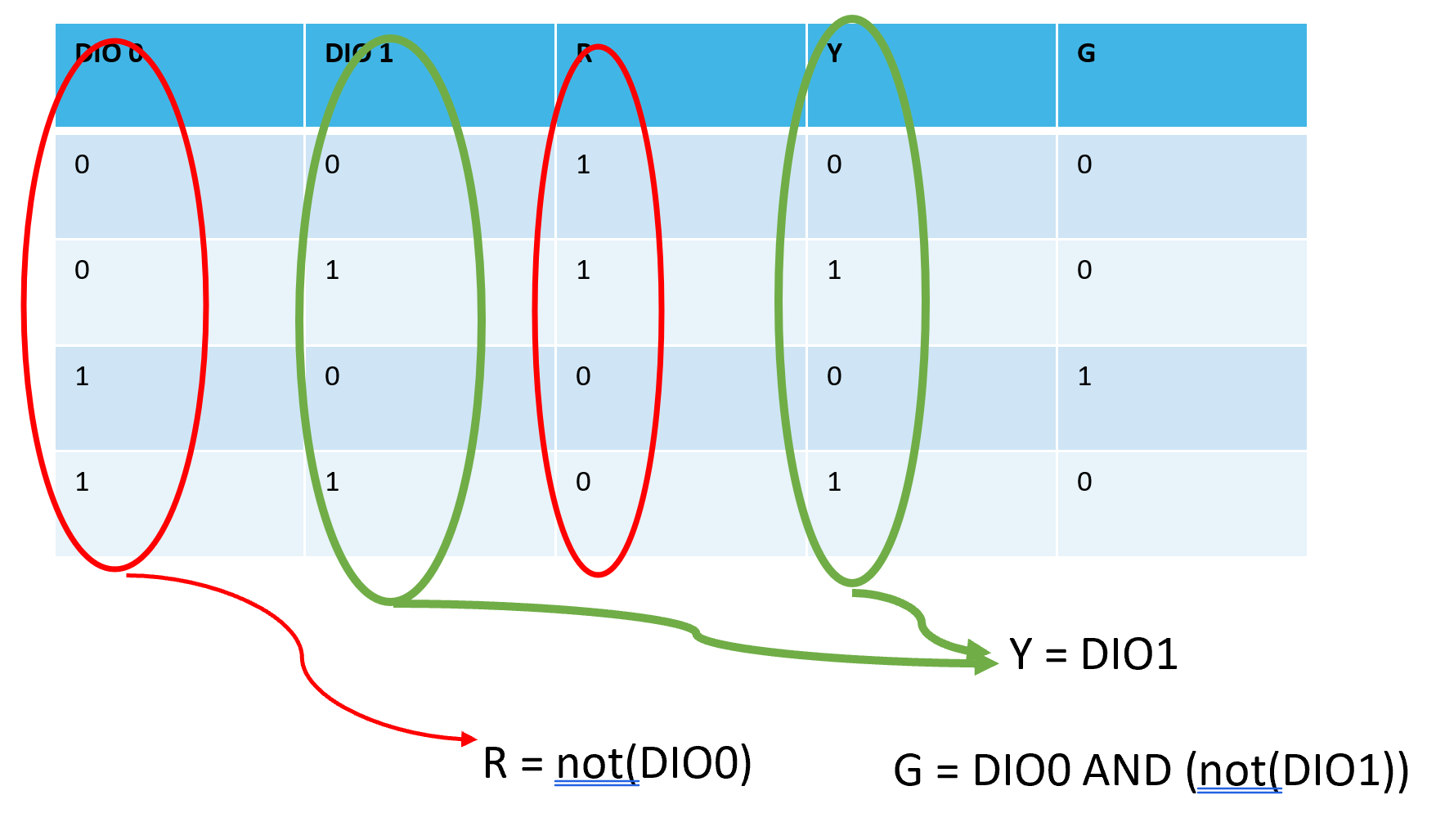
Truth table for the logic function that describes the traffic lights sequence
Hardware Setup
The circuit functionality is represented in the schematic:
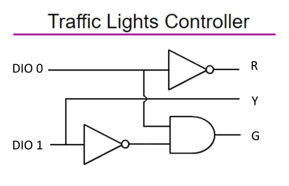
Components Pinout
Steps:
Place the ICs on the breadboard with each pin row on one side of the breadboard delimitator.
Open Scopy application
Open the Oscilloscope instrument
Open the Power instrument
Connect the V+ wire to pins 14 of the both ICs - VCC
Connect GND pin of the M2K to pin 7 of both ICs
Connect DIO 0 pin to SN74HC04N pin 1
Connect DIO 0 pin to SN74HC08N pin 1
Connect DIO 1 pin to SN74HC04N pin 3
Connect DIO 1 pin to Y LED
Connect SN74HC04N pin 2 to R LED
Connect SN74HC04N pin 4 to SN74HC08N pin 2
Connect SN74HC08N pin 3 to G LED
Set the V+ to 3.3V and press the Enable button
Results
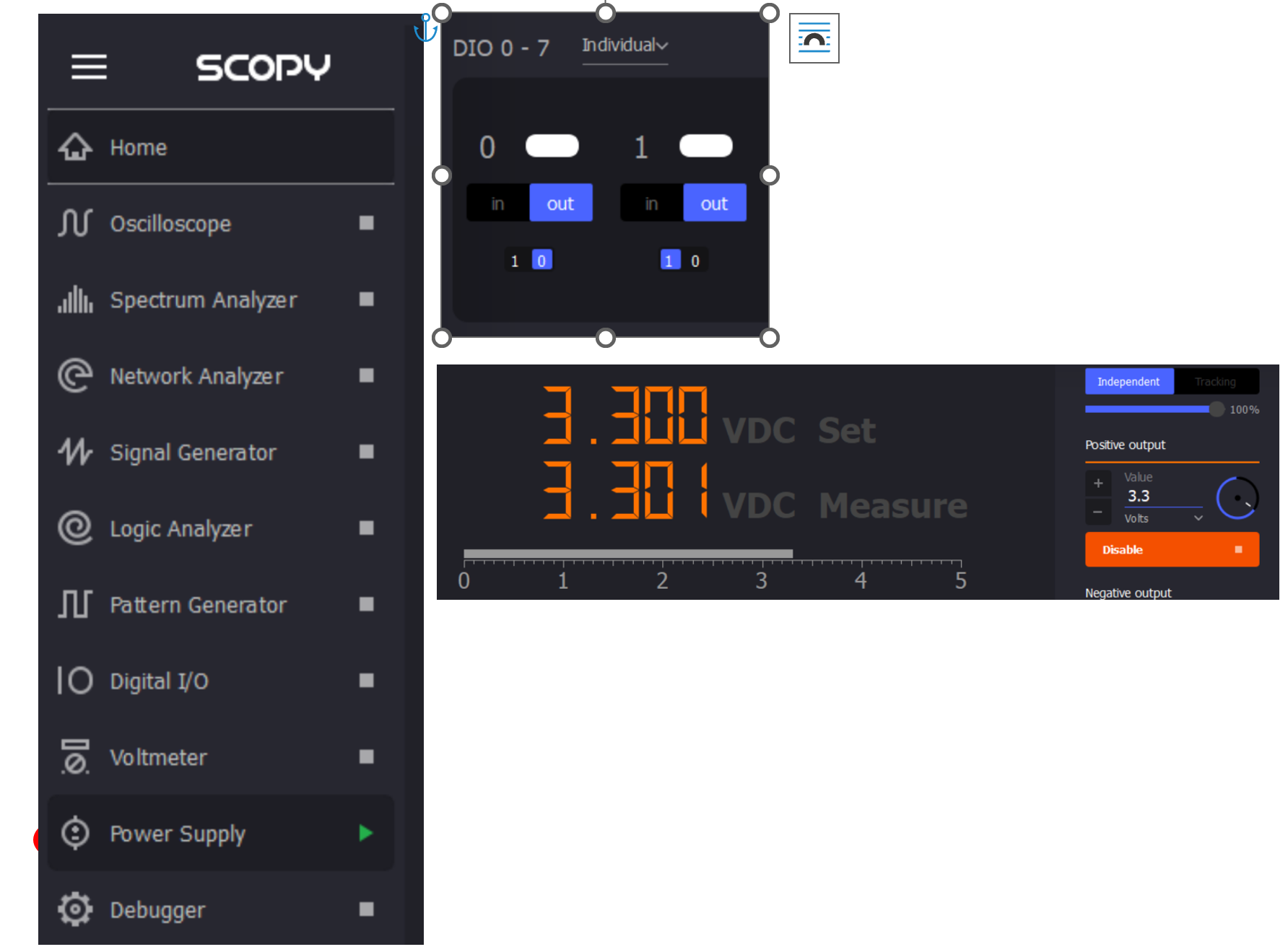
Open the Scopy Digital IO and Power instruments:
Toggle the DIO0 and DIO1 digital pins according to the logical function truth table and verify the outputs match the table results
Challenge
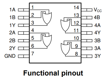
Implement a logical OR function using SN74HC32N part from the kit
Pinout:
Hands-on activity 3 - NPN transistor characteristics
The demo will describe the output characteristics of a BJT NPN transistor using modern instrumentation tools.
Materials
ADALM2000 Active Learning Module
Jumper wires
1 - 100KΩResistor
1 - 100ΩResistor
1 - small signal NPN transistor - 2N3904
1 - small signal PNP transistor - 2N3906
Theory of operation
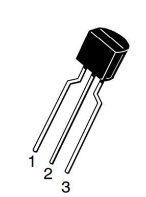
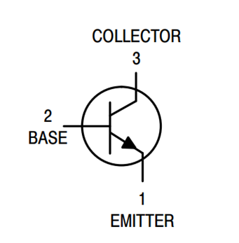
2N2904 Pinout
Hardware setup
Place the transistor and resistors on the breadboard.
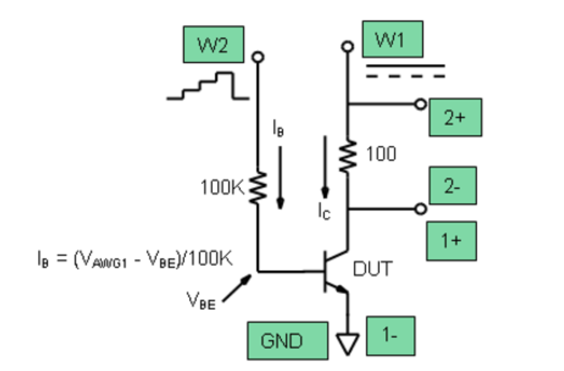
Make the connections between ADALM2000 and circuit as shown below.
Steps
Open Scopy application
Create a CSV file with a column having integer values from 0 to 5(0, 1, 2, 3, 4), save it
Open the Waveform generator instrument and select Channel 2, load the previously created csv file and make the setup:
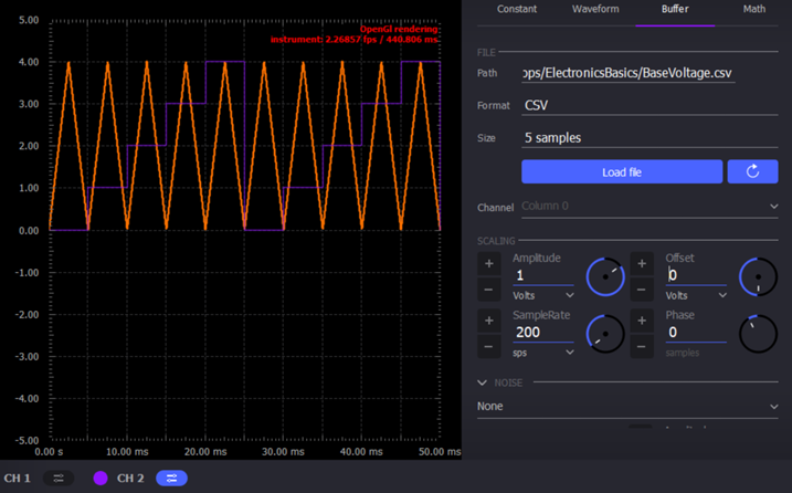
Select Channel 1, make the setup below:
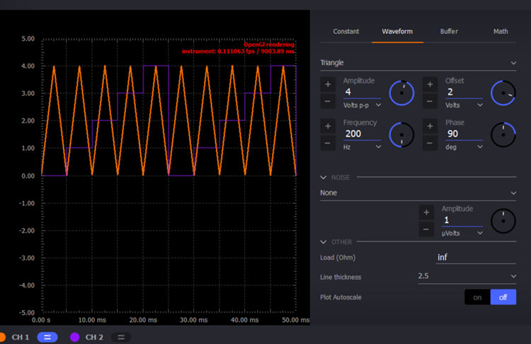
Open the scope and select the XY view
Add a math channel with the following function: M1 = t0/100 - it represents the Ic current, given the 100 ohms collector resistor
Results
Observe the output characteristics of the NPN transistor Ic = f(Vce)
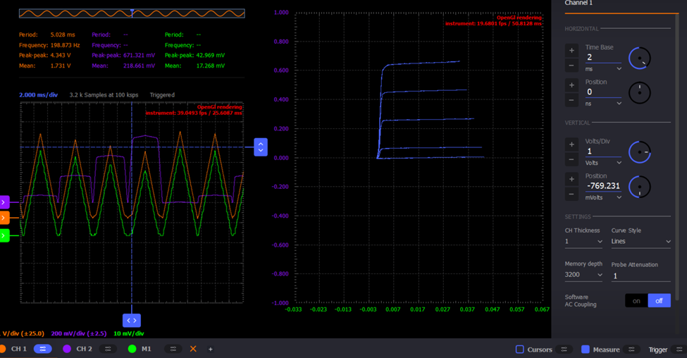
Challenge
Obtain the characteristics for a PNP transistor provided.
The curve trace should look like the one in the image:
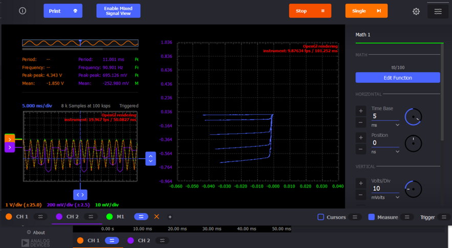
Tips: you need to create another csv file for the base control signal of the transistor.
Hands-on activity 4 - Home made battery - instructor-led
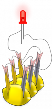
This demo is instructor-led and intends to implement a proof of concept for a battery powered LED using unconventional materials.
Materials:
ADALM2000 Active Learning Module
Jumper wires (wires with alligator clips will work best)
3 lemons: large, fresh, “juicy” lemons work best.
Zinc plated screws or nails
Copper plated coins or copper nails or heavy gauge (14 or 12) copper wire.
Red LED
Hardware Setup
Insert a copper penny into a small cut or push a copper nail or heavy gauge wire into one side of the lemon.
Push a galvanized (zinc coated) screw or nail into the other side of the lemon. The zinc and copper electrodes must not touch.
Results
You should be able to observe how the Red LED is lit by the 4 or more lemon-cells battery
Slide Deck, booklet and additional materials
Since this tutorial is also designed to be presented as a live, hands-on workshop, a slide deck is provided here:
A complete booklet of the hands-on activity is also provided, as a companion to following the tutorial yourself:
Download
Comma Separated Values file used for generating the base step voltage needed for the Transistor Characteristic demo:
Download
Base Voltage Values
Takeaways
Electronics can be both fun and challenging, but it brings many satisfactions
ADALM2000 is a very versatile tool suited to use in various applications:
Lab setups
Advanced measurements
Learning platforms
Research
Resources
Specific hardware resources
Inspiration
