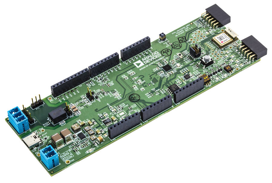
AD-APARD32690-SL
Arduino Form-factor Development Platform Based on MAX32690 ARM Cortex-M4.
Introduction
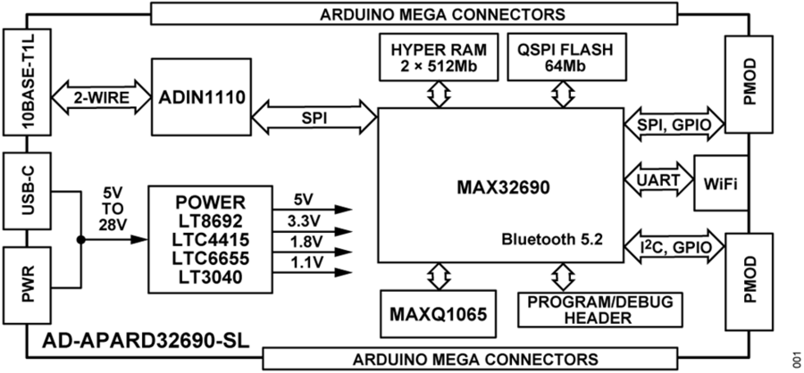
The AD-APARD32690-SL is an Arduino Form-factor Development Platform based on MAX32690 ARM Cortex-M4 Microcontroller, targeted for prototyping intelligent, secure, and connected industrial field devices. Some of the main features and benefits include:
Arduino Mega-compatible form factor
Two Pmod™-compatible connectors
ARM Cortex-M4 Ultra Efficient Microcontroller with integrated Bluetooth 5.2 LE
WiFi connectivity
Long-range, single-pair 10BASE-T1L Ethernet interface
Built-in security for root-of-trust, mutual authentication, data confidentiality and integrity, secure boot, and secure communications
Open-source software stack
Hardware design files:
Package Contents
The development kit is delivered with a set of accessories required to put the system together and get it up and running in no time.
This is what you’ll find in the development kit box:
1 x AD-APARD32690-SL board
1 x AD-T1LUSB2.0-EBZ 10BASE-T1L to USB adapter board
1 x PROFIBUS (1x2x18AWG) cable for Single Pair Ethernet (SPE) connectivity
1 x USB 2.0 cable
Application Development
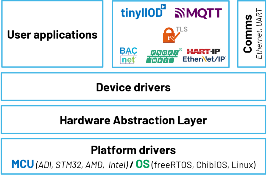
The AD-APARD32690-SL firmware is based on ADI’s open-source no-OS framework. It includes the bare-metal device drivers for all the components in the system as well as example applications enabling connectivity via the 10BASE-T1L interface for system configuration and data transfer.
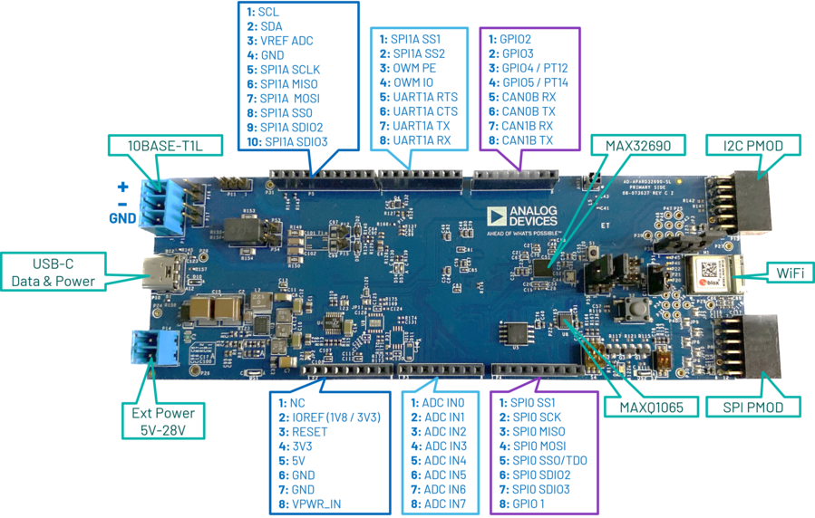
Hardware Components and Connections
Attention
TO BE REPLACED!
LEDs |
|
DS1 |
Power good |
DS2 |
User LED |
Buttons & Switches |
|
S1 |
MAX32690 Reset |
S2 |
User Button |
S3 |
User switches |
S4 |
1: ADIN1110 SWPD_EN |
2: ADIN1110 SPI_CFG0 |
|
3: ADIN1110 SPI_CFG1 |
|
Jumper settings |
|
P50 |
Position 1-2: Connect programmer SWD_RX to WiFi UART TX |
Position 2-3: Connect programmer SWD_RX to MAX32690 |
|
P55 |
Position 1-2: Connect programmer SWD_TX to WiFi UART RX |
Position 2-3: Connect programmer SWD_RX to MAX32690 |
|
P38 |
Connect WiFi UART TX to MAX32690 |
P56 |
Connect WiFi UART RX to MAX32690 |
P51 |
Position 1-2: Set programmer voltage to 3V3 (normal operation mode) |
Position 2-3: Set programmer voltage to 1V8 (WiFi chip programming) |
|
JP12 |
Position 1-2: To use the Low Power UART0RX port for programming and debugging |
Position 2-3: to use the normal UART0RX port for programming and debugging |
|
JP13 |
Position 1-2: To use the Low Power UART0TX port for programming and debugging |
Position 2-3: to use the normal UART0TX port for programming and debugging |
|
Connectors |
|
P1 |
10BASE-T1L |
P10 |
USB-C Power & Data |
P14 |
External Power 5V-28V |
P9 |
SWD Programmer |
P58 |
RISC-V Programmer |
P11 |
SPOE Shield ISO GND |
P16 |
SPOE Shield PI+ |
P17 |
SPOE Shield PI- |
P53 |
SPOE Shield PI+ |
P54 |
SPOE Shield PI- |
P12 |
SPOE Shield Data TRX N |
P15 |
SPOE Shield Data TRX P |
P8 |
SPI PMOD |
P13 |
I2C PMOD |
P2 |
Arduino Connector - Power |
P3 |
Arduino Connector - Analog |
P4 |
Arduino Connector - SPI / I2S |
P5 |
Arduino Connector - SPI & I2C |
P6 |
Arduino Connector - UART |
P7 |
Arduino Connector - GPIO & CAN |
Hardware Setup
Required Hardware
Development kit: AD-APARD32690-SL Microcontroller Board
Power supplies: 5V to 28V at 2A external power supply or 5V USB-C power supply
Programmer: MAX32625PICO or any other similar programmer supporting the SWD interface
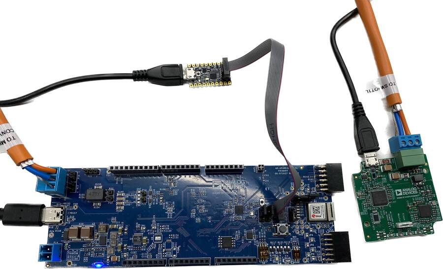
Connect the AD-APARD32690-SL to the AD-T1LUSB2.0-EBZ using the single pair Ethernet cable.
Connect the AD-T1LUSB2.0-EBZ to your PC using an USB cable.
Connect the MAX32625PICO programmer, or any programmer supporting the SWD interface, to the AD-APARD32690-SL.
Connect the power supply to the AD-APARD32690-SL.
Software Setup
Updating the AD-APARD32690-SL Firmware
To update the board’s firmware, a new bootloader has to be flashed on the MAX32625PICO.
Download the firmware image: MAX32625PICO firmware
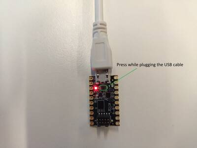
Set the MAX32625PICO in MAINTENANCE mode:
Disconnect the MAX32625PICO from the PC and the AD-SWIOT1L-SL board.
Plug the micro USB cable only in the MAX32625PICO.
Keep the button on the MAX32625PICO pressed.
Plug the micro USB cable into the PC.
Once you see the MAINTENANCE drive being mounted, you may release the button.
Drag and drop (to the MAINTENANCE drive) the firmware image you previously downloaded.
After a few seconds, the MAINTENANCE drive will disappear and will be replaced by a drive named DAPLINK. Once this is done, the process is complete, and the MAX32625PICO may be used to flash the firmware of the AD-SWIOT1L-SL board.
Programming the AD-APARD32690-SL
Connect the MAX32625PICO to the PC using the micro USB cable.
Connect the MAX32625PICO to the AD-APARD32690-SL board using the 10-pin ribbon cable.
Connect the power supply to the AD-APARD32690-SL. Make sure the board is powered up for the next steps.
A DAPLINK drive should appear as mounted on your PC.
Drag and drop the new firmware image into the DAPLINK drive. After a few seconds, the drive will be remounted.
Check the DAPLINK directory and make sure there is no FAIL.TXT file. In case there is, repeat the drag and drop step. Otherwise, you may disconnect the MAX32625PICO from the AD-APARD32690-SL, since the firmware update is complete.
AD-APARD32690-SL Software Stack
The system is accompanied by an open-source software stack and associated collateral, enabling a complete experience from evaluation and prototyping all the way to production firmware and applications development.
The AD-APARD32690-SL firmware is based on Analog Devices’ open-source no-OS framework, which includes all the tools required for embedded code development and debugging as well as libraries enabling host-side connectivity for system configuration and data transfer over the UART or the 10BASE-T1L interfaces. The firmware source code and related documentation can be found on the Analog Devices GitHub at the link above.
User Guide
Help and Support
For questions and more information, please visit the EngineerZone.