Using with Raspberry Pi
Required Hardware
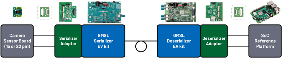
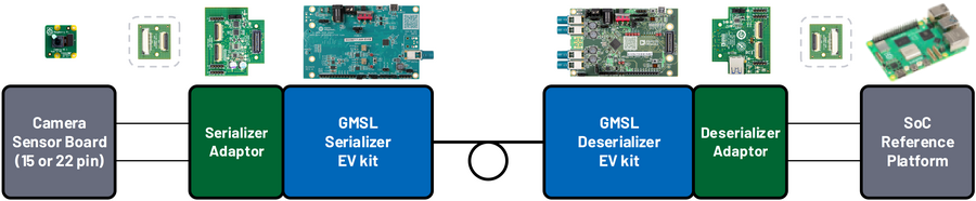
Development Kits
MAX96717 GMSL Serializer Evaluation Kit or GMSL camera
Raspberry Pi 4 Model B (2GB of RAM or more preferred) or Raspberry Pi 5 (2GB of RAM or more preferred)
Supported Image Sensors & Cameras
Cables
Warning
Do not use the 15-pin ribbon cable included with the Raspberry Pi camera since that is an opposite sided cable.
Raspberry Pi 4:
15-Pin Type A (same side) Flexible Ribbon Cable, P/N: MP-FFCA10152003A or similar
22-Pin Type B (opposite side) Flexible Ribbon Cable, P/N: MP-FFCA05222002B or similar
FAKRA Jack to FAKRA Jack coaxial cable, provided in EV kits
Raspberry Pi 5:
15-Pin Type A (same side) Flexible Ribbon Cable, P/N: MP-FFCA10152003A or similar
22-Pin Type B (opposite side) Flexible Ribbon Cable, P/N: MP-FFCA05222002B or similar
22-Pin Type A (same side) Flexible Ribbon Cable, P/N: MP-FFCA05222002A or similar
FAKRA Jack to FAKRA Jack coaxial cable, provided in EV kits
Board Modifications
Using the procedure to Set CFG Pin Levels, configure the SerDes pair as follows:
Pin |
MAX96717 |
MAX96724 |
CFG0 |
0 – I2C, ROR, 0x80 |
0 – I2C, 0x4E |
CFG1 |
7 – Coax, 6 Gbps, Pixel |
0 – Coax, GMSL2, 6Gbps |
Important
It is required to set the CFG pins to the indicated levels for this setup.
For more information about the default CFG configuration of each evaluation board, please visit the respective datasheet documentation:
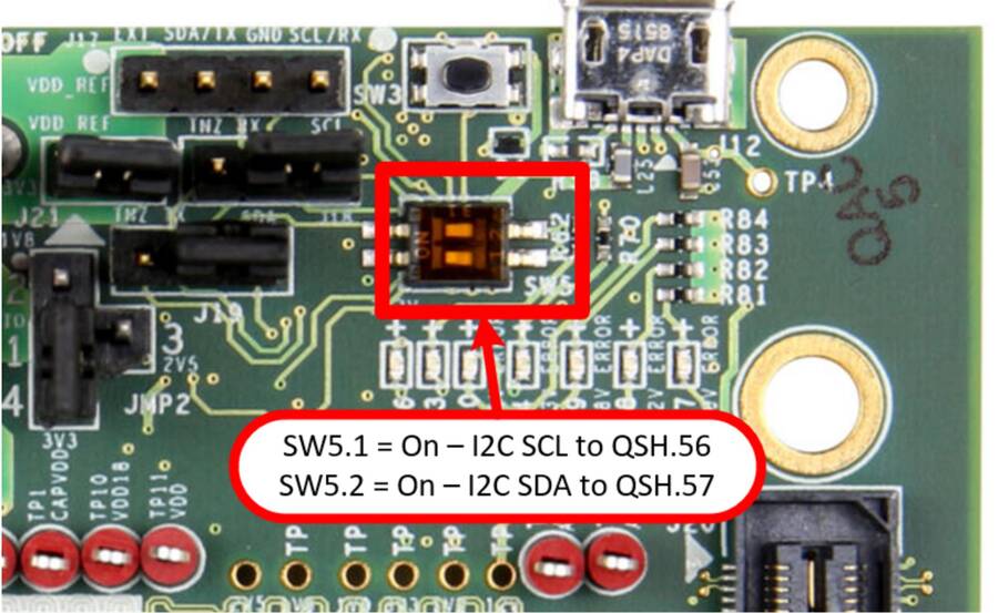
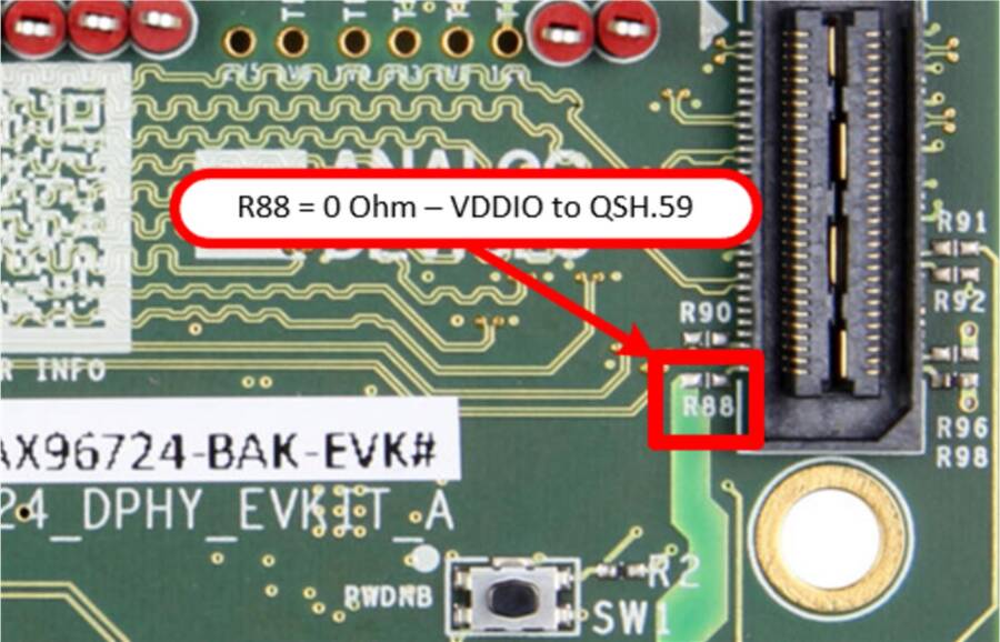
GMSL Deserializer Evaluation Kit
Slide the SW5 switches to the ON position to enable I2C communication over the CSI bus
Remove the J18 and J19 jumpers to allow the RPi to become the Main host controller for the I2C lines
Make sure the J3 is set as default 2-3 position to enable POC
Bridge R88 - provides VDDIO to the adapter
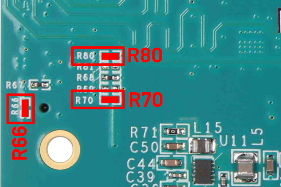
GMSL Serializer Evaluation Kit
Place a jumper on the J10 connector to enable power over the coaxial cable
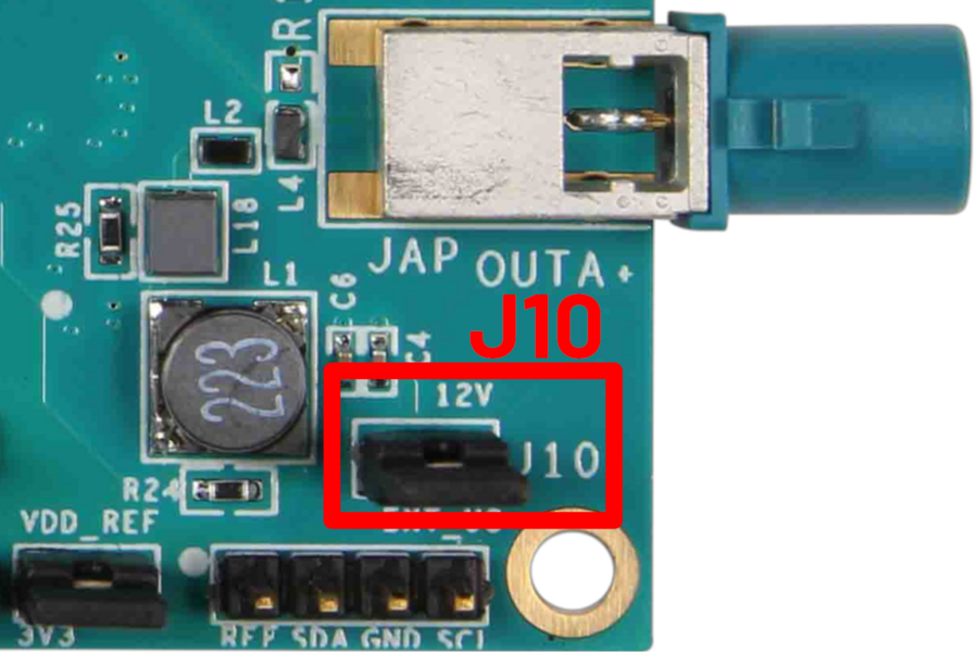
Bridge R70 - provides 12V to the adapter
Bridge R80 - connects MFP2 to the adapter for IMX219
Bridge R66 - provides VDDIO to the adapter
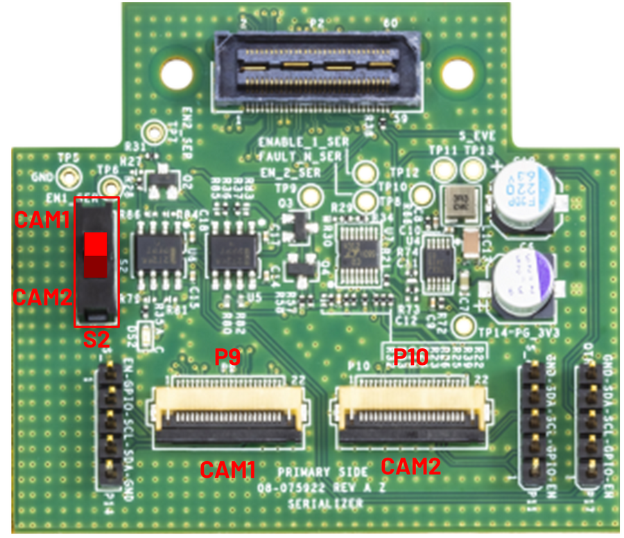
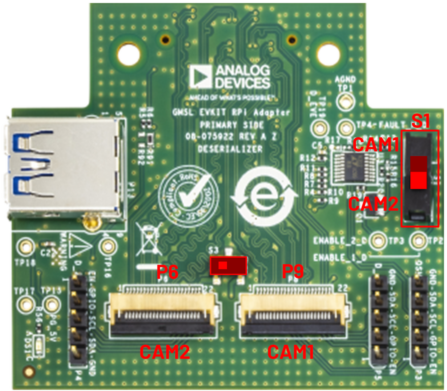
AD-GMSLCAMRPI-ADP# Adapter
Configure the switch S2 on the GMSL Serializer adapter for CAM1 on connector P9
Configure the switch S1 on the GMSL Deserializer adapter for CAM2 on connector P6 and slide switch S3 towards connector P6
Serializer Adapter
Deserializer Adapter
System Setup
MAX96717 Serializer EV Kit Configuration
For the following setup, please ensure ribbon cables and boards are oriented to match the diagrams.
Connect the 15-pin ribbon cable to the camera board.

Connect the other end of the 15-pin ribbon cable into the 15- to 22-pin adapter board.
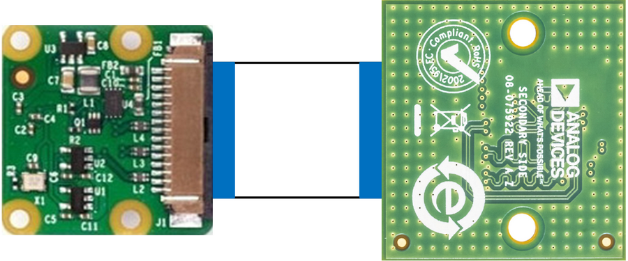
Figure 10 Connect the 15-pin Ribbon Cable to the GMSL Adapter Board (opposite side)
On the other side of the 15- to 22-pin adapter board, connect the 22-pin opposite-sided ribbon cable.
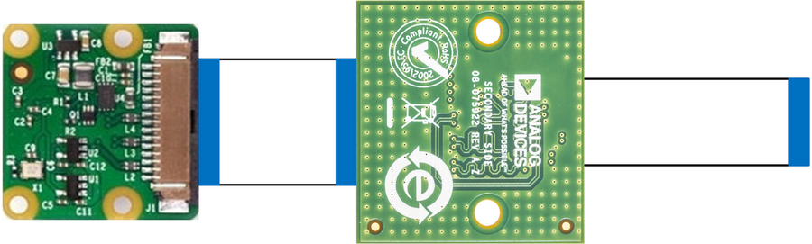
Figure 11 Connect the 22-pin Opposite-Sided Ribbon Cable to the GMSL Adapter Board
Connect the other end of the 22-pin opposite-sided ribbon cable into the EV Kit adapter board P9 connector.
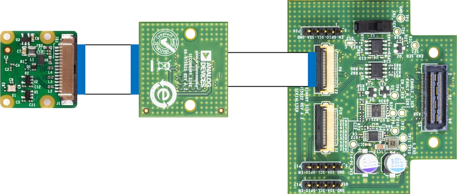
Figure 12 Connect the 22-pin Opposite-Sided Ribbon Cable to the EV Kit Adapter Board (opposite side)
Lastly, connect the EV kit adapter board to the MAX96717 EV Kit.
Figure 13 Connect the EV Kit Adapter Board to the MAX96717 Serializer EV Kit
MAX96724 Deserializer EV Kit Configuration
Raspberry Pi 4
Starting with the Raspberry Pi 4B, connect the 15-pin ribbon cable to the CSI input connector.
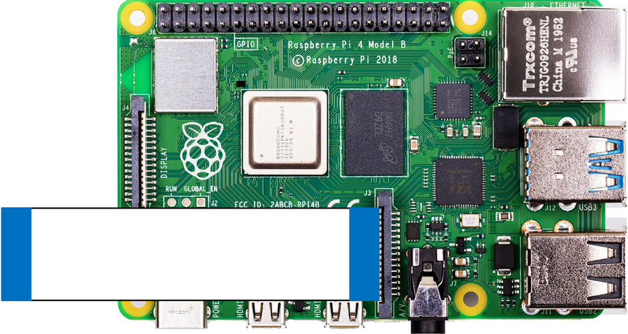
Figure 14 Connect the 15-pin Ribbon Cable to the Raspberry Pi
Connect the other end of the 15-pin ribbon cable into the 15- to 22-pin adapter board.
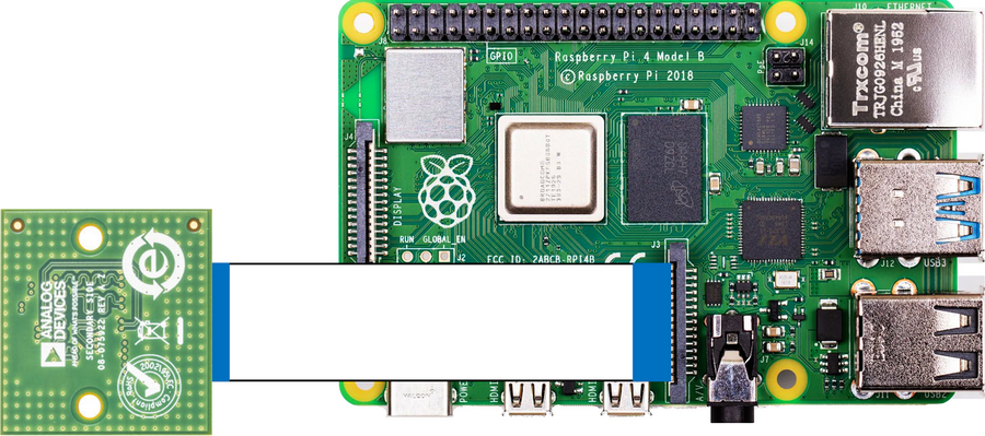
Figure 15 Connect the 15-pin ribbon cable into the GMSL Adapter Board (opposite side)
On the other side of the 15-to-22 pin adapter board, connect the 22-pin opposite-sided ribbon cable.
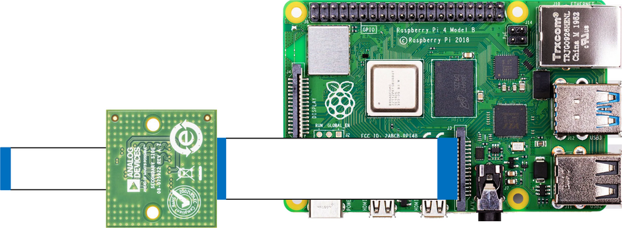
Figure 16 Connect the 22-pin Opposite-Sided Ribbon Cable to the GMSL Adapter Board
Connect the other end of the 22-pin opposite-sided ribbon cable into the EV kit adapter board P6 connector.
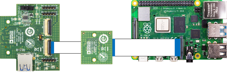
Figure 17 Connect the 22-pin Opposite-Sided Ribbon Cable to the EV Kit Adapter Board
Lastly, connect the EV kit adapter board to the MAX96724 EV kit.
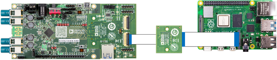
Figure 18 Connect the EV Kit Adapter Board to the MAX96724 Deserializer EV Kit
With both sides of the SerDes devices connected up, the last step is to connect the two sides together with the coax cable. The MAX96717 serializer only has one connection. The MAX96724 deserializer has 4 inputs so connect the coax cable to link A (INA) on J7.
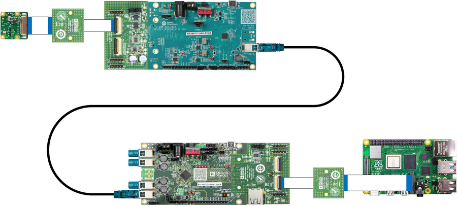
Connect power to the 12V barrel jack J1 of the MAX96724 deserializer. If utilizing the GMSL GUI, also connect the micro USB cable to J6 of the MAX96724 deserializer EV kit.
Raspberry Pi 5
Starting with the Raspberry Pi 5, connect the 22-pin same-sided ribbon cable to the CSI input connector on J3.
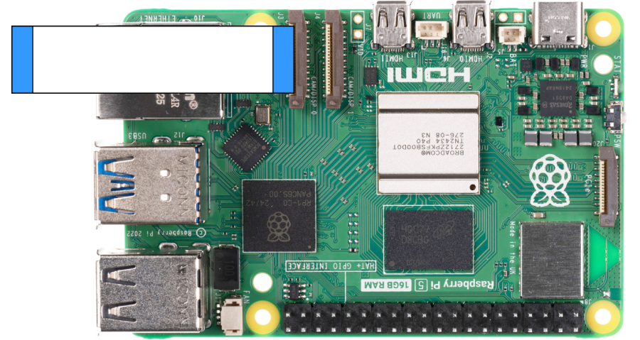
Figure 20 Connect the 22-pin Same-Sided Ribbon Cable to the Raspberry Pi
Connect the other end of the 22-pin same-sided ribbon cable into the EV kit adapter board P6 connector.
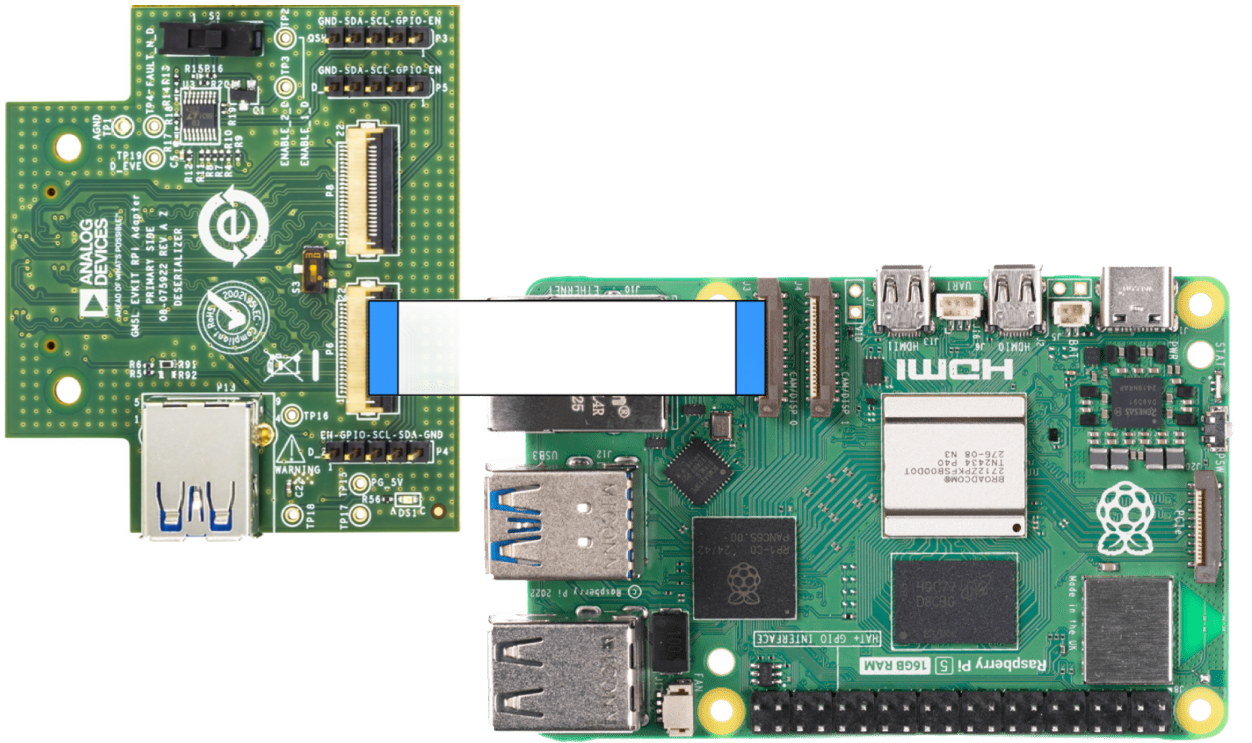
Figure 21 Connect the 22-pin Same-Sided Ribbon Cable to the EV Kit Adapter Board
Lastly, connect the EV kit adapter board to the MAX96724 EV kit.
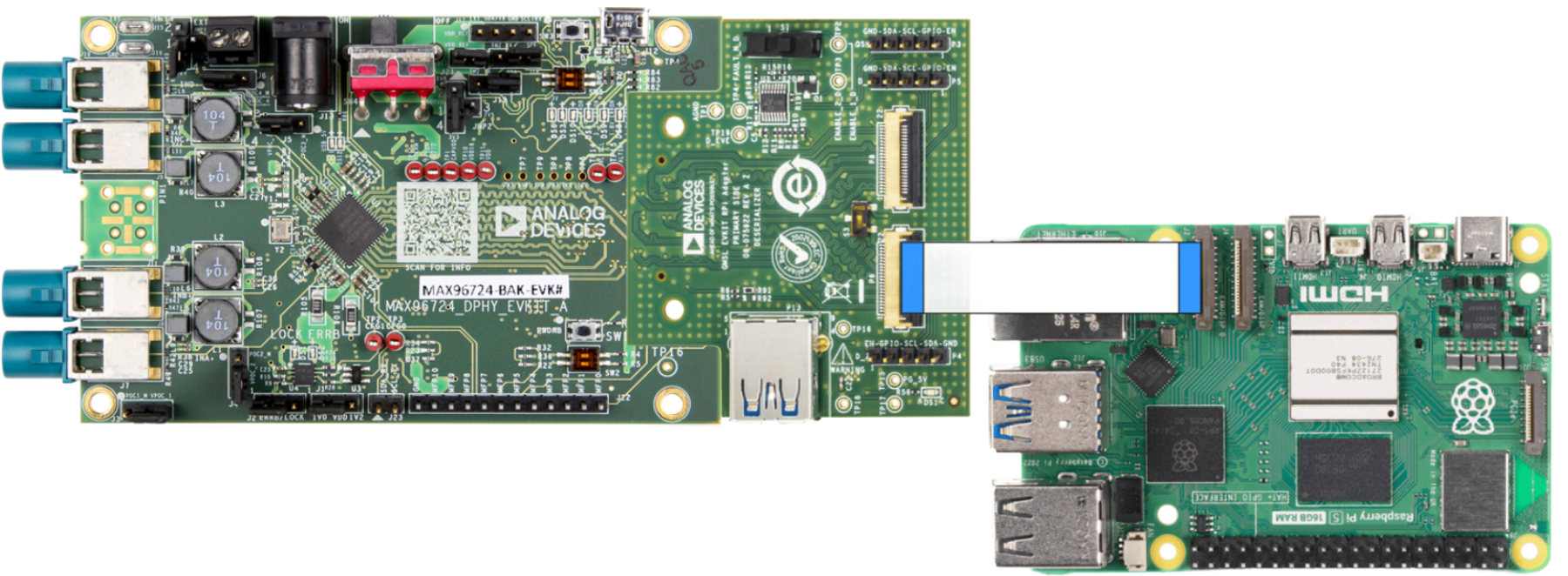
Figure 22 Connect the EV Kit Adapter Board to the MAX96724 Deserializer EV Kit
With both sides of the SerDes devices connected up, the last step is to connect the two sides together with the coax cable. The MAX96717 serializer only has one connection. The MAX96724 deserializer has 4 inputs so connect the coax cable to link A (INA) on J7.
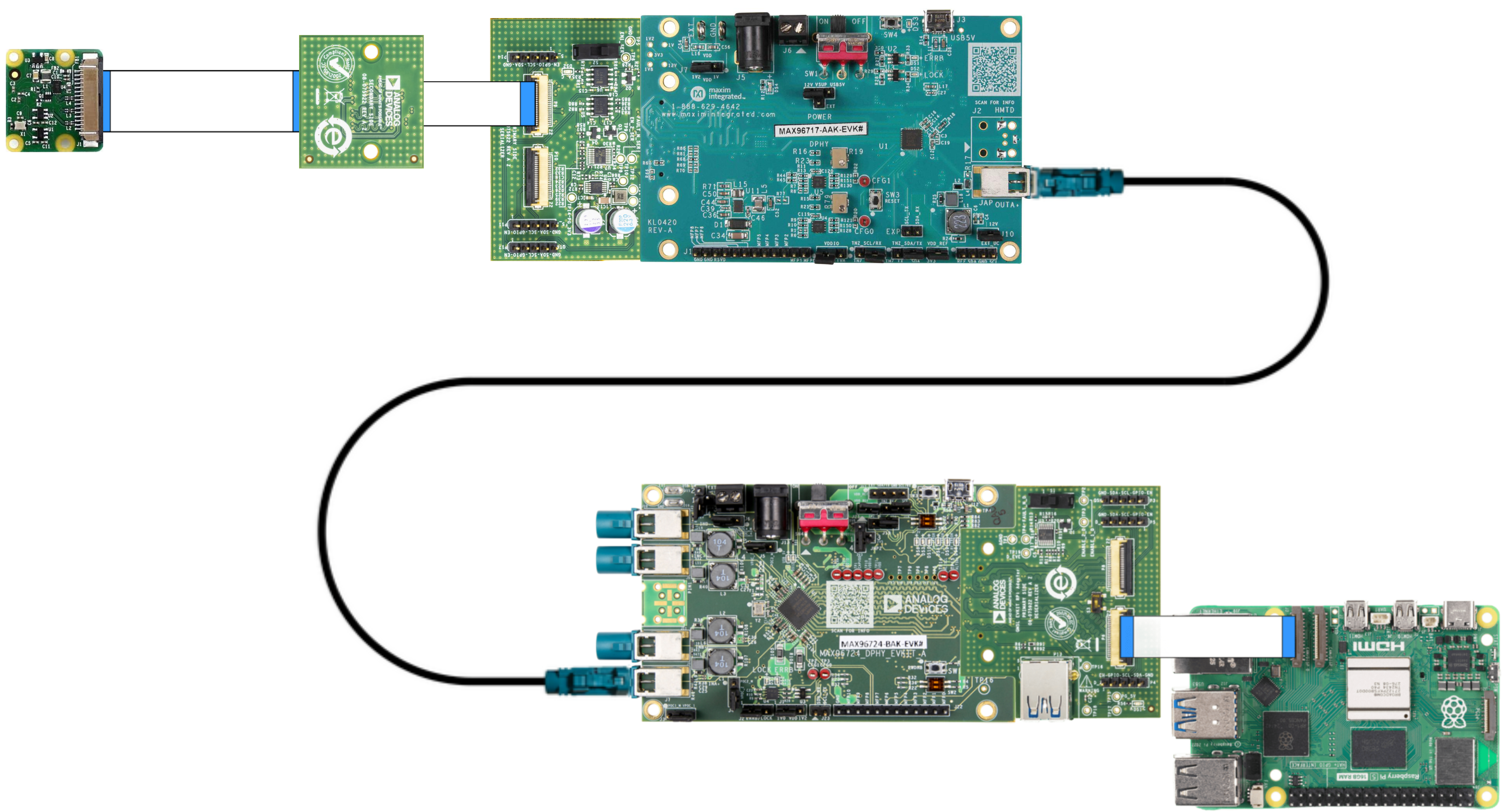
Connect power to the 12V barrel jack J1 of the MAX96724 deserializer. If utilizing the GMSL GUI, also connect the micro USB cable to J6 of the MAX96724 deserializer EV kit.
Raspberry Pi Configuration
Connect the USB-C power supply to the Raspberry Pi connector
Connect the HDMI cable from the monitor to the Raspberry Pi micro HDMI connector
Write the Raspberry Pi latest SD card image on an 8 GB (or more) SD card
Plug the SD card into the Raspberry Pi SD card slot
Connect a USB mouse and keyboard to the Raspberry Pi (it is possible to use either a mouse & keyboard combo or a separate mouse and keyboard)
Running the Evaluation Application
Once Linux boots, you will see the Linux desktop on the HDMI monitor.
1. Configuring Cameras
You can either run the configuration command directly (option a) or create a reusable script (option b).
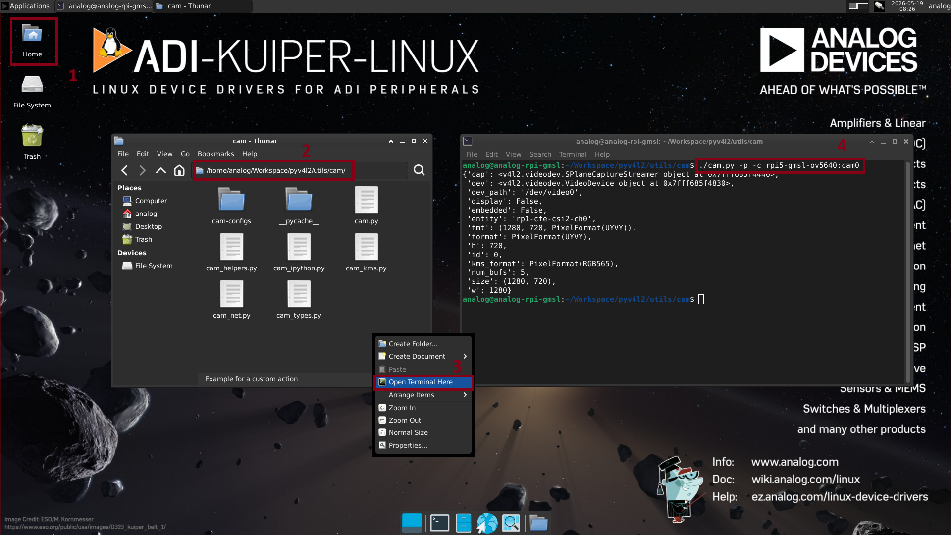
a) Running the configuration command directly
Double-click the Home icon and navigate to the Workspace/pyv4l2/utils/cam folder. Right-click inside this folder and select the Open Terminal Here option. Inside the terminal, type the following command and hit Enter. Make sure to change the command parameters according to your setup:
RPI_MODEL(specifies the model of the Raspberry Pi):
rpi4
rpi5
CAM_MODEL(specifies the model of the camera):
imx219
ov5640
CAM_LIST(specifies the list of cameras in the setup):
cam0
cam0,cam1
cam0,cam1,cam2
cam0,cam1,cam2,cam3
cam1,cam2
cam0,cam3
~$
./cam.py -p -c <RPI_MODEL>-gmsl-<CAM_MODEL>:<CAM_LIST>
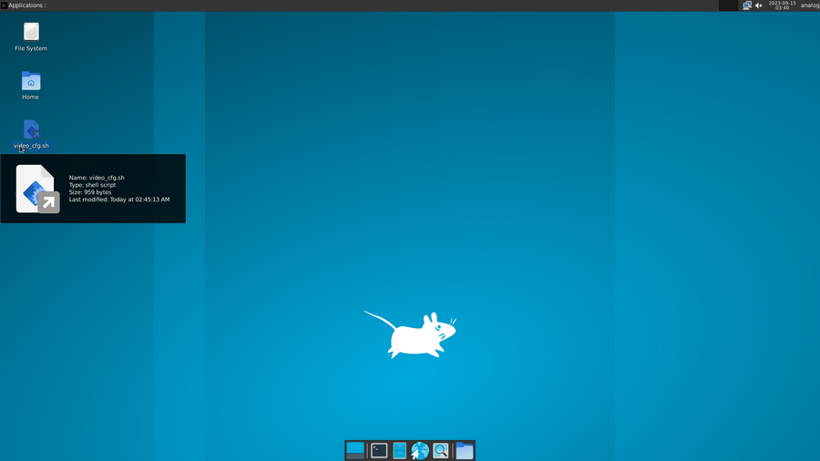
b) Creating a video configuration script
Alternatively, you can create a reusable script. Double-click the Home icon
and navigate to the Workspace folder. Create a new file named
video_cfg.sh and copy-paste the following content into the file:
#!/bin/bash

CAM_LIST="cam0"
CAM_MODEL="imx219"
PYV4L2_PATH="/home/analog/Workspace/pyv4l2"
DT_MODEL_PATH="/proc/device-tree/model"

if [[ $(cat $DT_MODEL_PATH | tr -d '\0') =~ "Raspberry Pi 4" ]]; then
   echo "Running on RPI4"
   RPI_MODEL="rpi4"
elif [[ $(cat $DT_MODEL_PATH | tr -d '\0') =~ "Raspberry Pi 5" ]]; then
   echo "Running on RPI5"
   RPI_MODEL="rpi5"
else
   echo "Unknown platform"
   exit 0
fi

$PYV4L2_PATH/utils/cam.py -c -p "$RPI_MODEL"-gmsl-"$CAM_MODEL":$CAM_LIST
This script configures the Linux V4L2 (Video4Linux2) media pipeline for a GMSL multi-camera system on a Raspberry Pi. It detects the Raspberry Pi model, sets the camera configuration, and runs a Python script to apply the settings.
The following variables can be changed (if needed) inside the script:
CAM_LIST(specifies the list of cameras in the setup):
cam0(default)
cam0,cam1
cam0,cam1,cam2
cam0,cam1,cam2,cam3
cam1,cam2
cam0,cam3
CAM_MODEL(specifies the model of the camera):
imx219(default)
ov5640
The model of the Raspberry Pi does not need to be explicitly specified because the script detects it automatically.
Make sure to change the permissions of the file to make it executable. To do this, right-click inside this folder and select the Open Terminal Here option. Inside the terminal, type the following command and hit Enter:
~$
chmod +x ./video_cfg.sh
To run the script, type the following command in the terminal and hit Enter:
~$
./video_cfg.sh
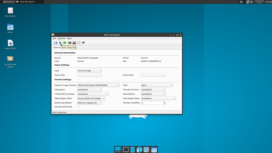
2. Starting Video Capture
After the camera configuration is done, click on Applications (found in the top left corner), which will open a dropdown list of items. From this list, select Multimedia and then Qt V4L2 test Utility in order to start the video capture application. After the application opens, press the green play button to start capturing video.
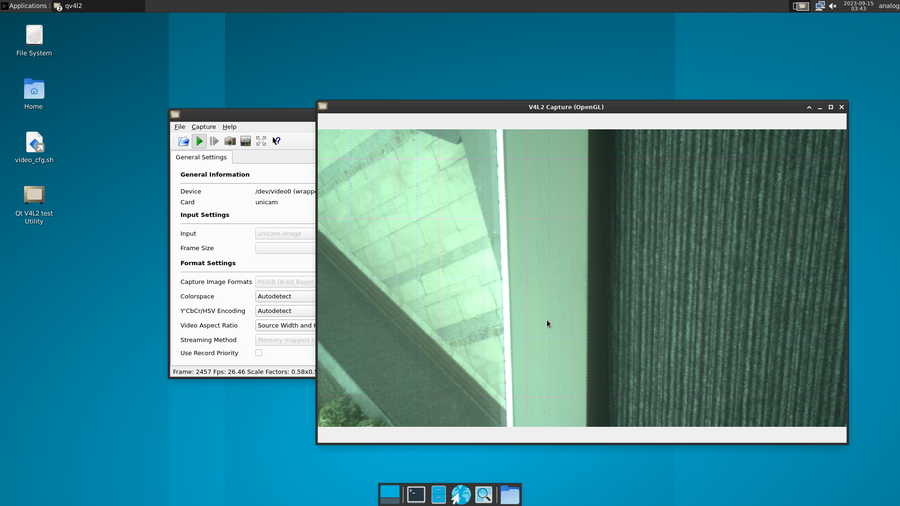
3. Viewing the Capture
The capture window will look as shown below.
Note
Some displays may have vertical/horizontal lines. This is typically an artifact caused on HDMI monitors and unrelated to the evaluation setup.
Power-off Sequence
Open a terminal and type sudo poweroff. This will safely power off the Raspberry Pi and ensure that the SD card is properly unmounted
Remove the power supply from the Raspberry Pi
Remove the power supply from the MAX96724 EV kit
Getting the Software
The GMSL Linux kernel drivers, the complete Linux distributions for the supported processing platforms, and software user guides can be found on the Analog Devices GMSL GitHub repository.
Tips for Troubleshooting
There are a few key commands in the Linux environment that can help identify if the expected connections and communications have been made.
In the Linux environment, you can check to see if the RPi I2C is detecting the GMSL boards by sending an I2C detect command [1] as follows:
~$
sudo i2cdetect -y 10
The result should look as follows in the terminal, if using the IMX camera:
user@kuiper-gmsl:~$
sudo i2cdetect -y 10
[sudo] password for analog:
     0  1  2  3  4  5  6  7  8  9  a  b  c  d  e  f
00:                         -- -- -- -- -- -- -- --
10: UU -- -- -- -- -- -- -- -- -- -- -- -- -- -- --
20: -- -- -- -- -- -- -- UU -- -- -- -- -- -- -- --
30: -- -- -- -- -- -- -- -- -- -- -- -- -- -- -- --
40: 40 -- -- -- -- -- -- -- -- -- -- -- -- -- -- --
50: -- -- -- -- -- -- -- -- -- -- -- -- -- -- -- --
60: -- -- -- -- 64 -- -- -- -- -- -- -- -- -- -- --
70: -- -- -- -- -- -- -- --
Or, as follows, if using the Pcam camera:
user@kuiper-gmsl:~$
sudo i2cdetect -y 10
[sudo] password for analog:
     0  1  2  3  4  5  6  7  8  9  a  b  c  d  e  f
00:                         -- -- -- -- -- -- -- --
10: -- -- -- -- -- -- -- -- -- -- -- -- -- -- -- --
20: -- -- -- -- -- -- -- UU -- -- -- -- -- -- -- --
30: -- -- -- -- -- -- -- -- -- -- -- -- 3c -- -- --
40: 40 -- -- -- -- -- -- -- -- -- -- -- -- -- -- --
50: 50 -- -- -- -- -- -- -- -- -- -- -- -- -- -- --
60: -- -- -- -- -- -- -- -- -- -- -- -- -- -- -- --
70: -- -- -- -- -- -- -- --
You can also confirm that the Video for Linux application is detecting the camera and GMSL devices by using the following command:
~$
v4l2-ctl --list-devicesRaspberry Pi 4
The response should look like the following:
~$
v4l2-ctl --list-devicesbcm2835-codec-decode (platform:bcm2835-codec): /dev/video10 /dev/video11 /dev/video12 /dev/video18 /dev/video31 /dev/media2 bcm2835-isp (platform:bcm2835-isp): /dev/video13 /dev/video14 /dev/video15 /dev/video16 /dev/video20 /dev/video21 /dev/video22 /dev/video23 /dev/media1 /dev/media3 unicam (platform:fe801000.csi): /dev/video0 /dev/video1 /dev/media4 rpivid (platform:rpivid): /dev/video19 /dev/media0Note
For Raspberry Pi 4, the key idea is to identify the unicam output, which corresponds to the Raspberry Pi camera setup.
Raspberry Pi 5
The response should look like the following:
~$
v4l2-ctl --list-devicespispbe (platform:1000880000.pisp_be):
     /dev/video20
     /dev/video21
     /dev/video22
     /dev/video23
     /dev/video24
     /dev/video25
     /dev/video26
     /dev/video27
     /dev/video28
     /dev/video29
     /dev/video30
     /dev/video31
     /dev/video32
     /dev/video33
     /dev/video34
     /dev/video35
     /dev/media0
     /dev/media1
rp1-cfe (platform:1f00110000.csi):
     /dev/video0
     /dev/video1
     /dev/video2
     /dev/video3
     /dev/video4
     /dev/video5
     /dev/video6
     /dev/video7
     /dev/media3
rpi-hevc-dec (platform:rpi-hevc-dec):
     /dev/video19
     /dev/media2