Software User Guide
Required Hardware
Development kit: AD-SWIOT1L-SL Software-configurable Analog and Digital I/O with 10BASE-T1L
Power supplies: 24V power supply at minimum 2A
Programmer: MAX32625PICO or any other similar programmer supporting the SWD interface
System Setup
Connect the AD-SWIOT1L-SL to the AD-T1LUSB2.0-EBZ using the single pair Ethernet cable.
Connect the AD-T1LUSB2.0-EBZ to your PC using a usb cable
Connect the 24 V power supply to the AD-SWIOT1L-SL.
Windows User Guide
Connect the AD-SWIOT1L-SL to your Windows PC using the AD-T1LUSB2.0-EBZ.
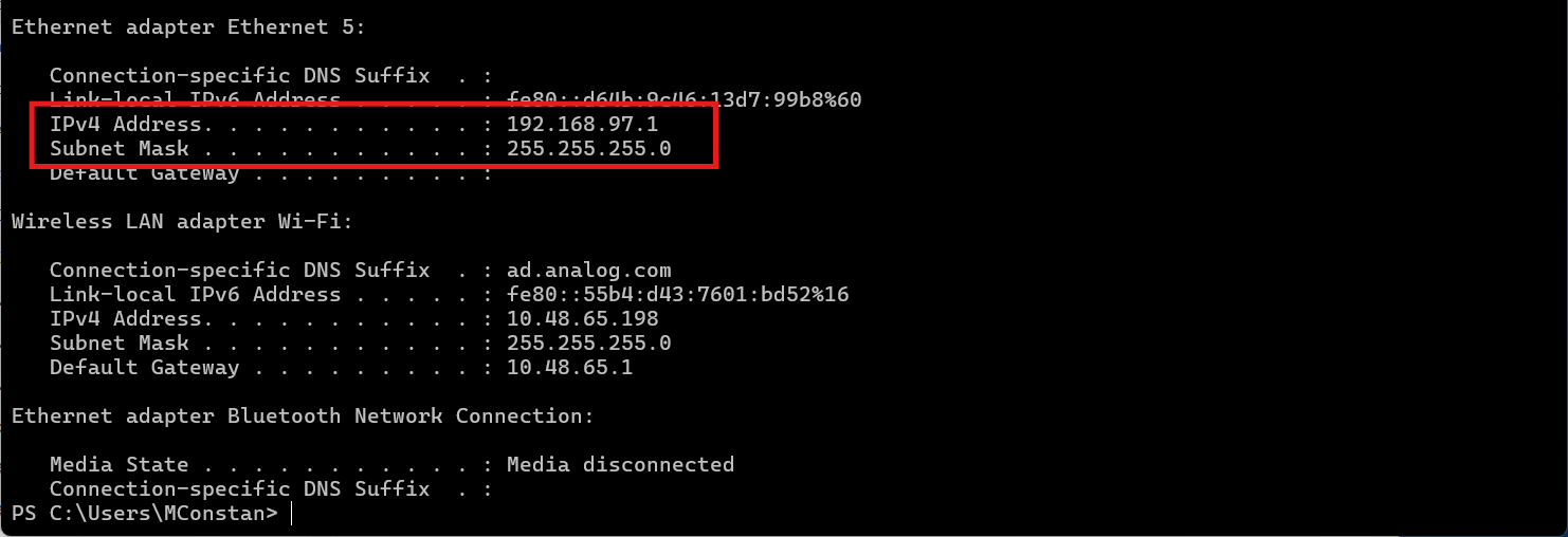
To communicate with the AD-SWIOT1L-SL board, you need to configure your Windows PC’s network adapter with a static ip address in the same subnet as the board e.g 192.168.97.1/24
The AD-SWIOT1L-SL board uses the static ip address: 192.168.97.40
Configure Windows Network Adapter
Open the Control Panel and navigate to “Network and Internet”
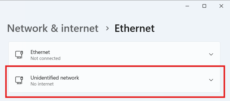
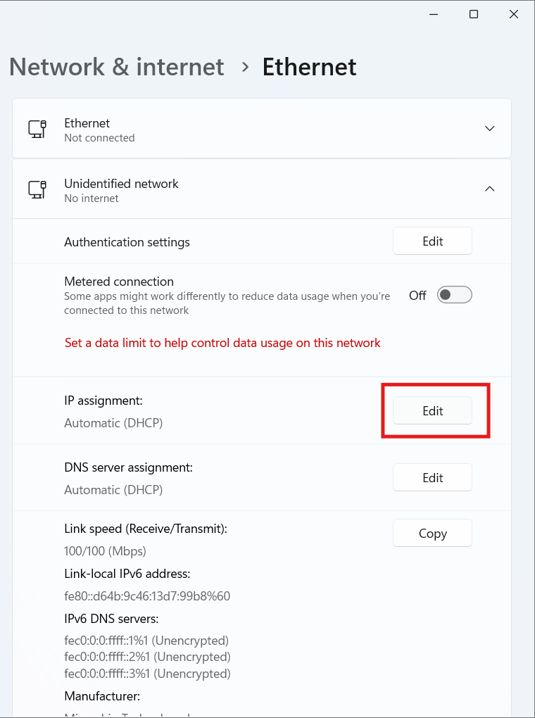
Select your Ethernet interface and click “Edit” to modify the ip settings
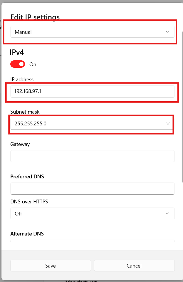
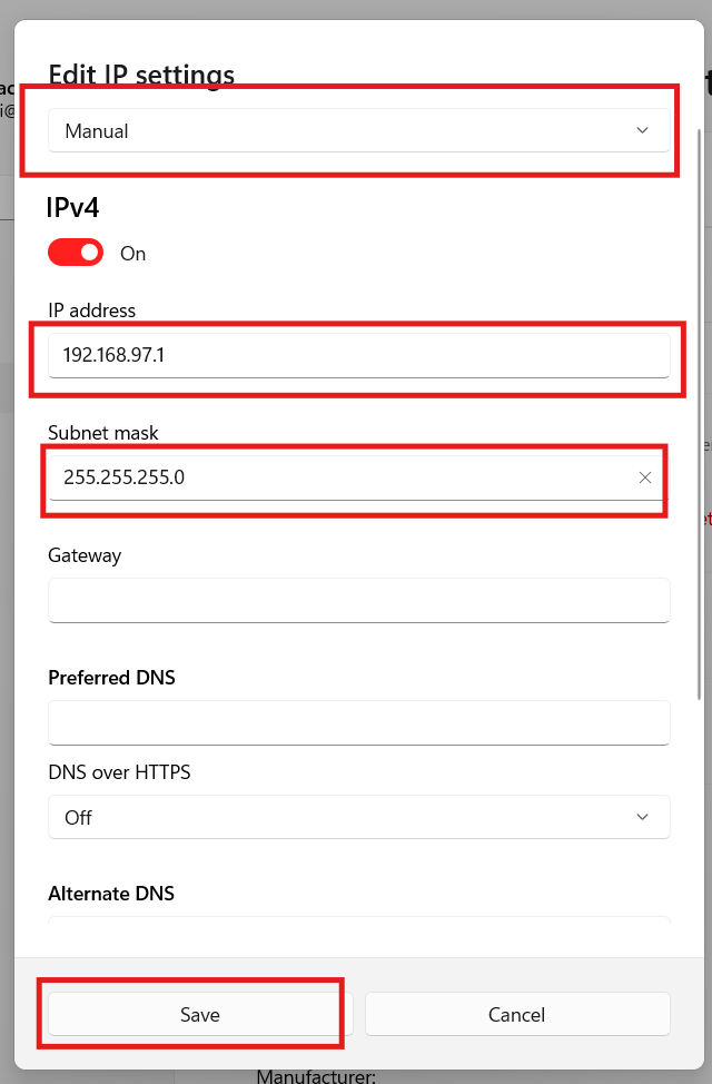
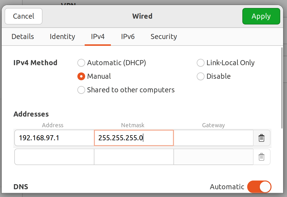
Set the ip settings to manual and configure the following values:
ip address: 192.168.97.1
Subnet mask: 255.255.255.0
Save the changes and close the network settings.
Open a command prompt and verify the new assigned ip address using the command:
ipconfig
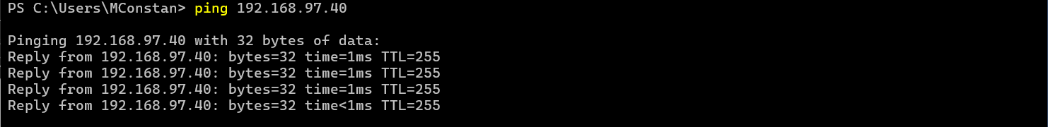
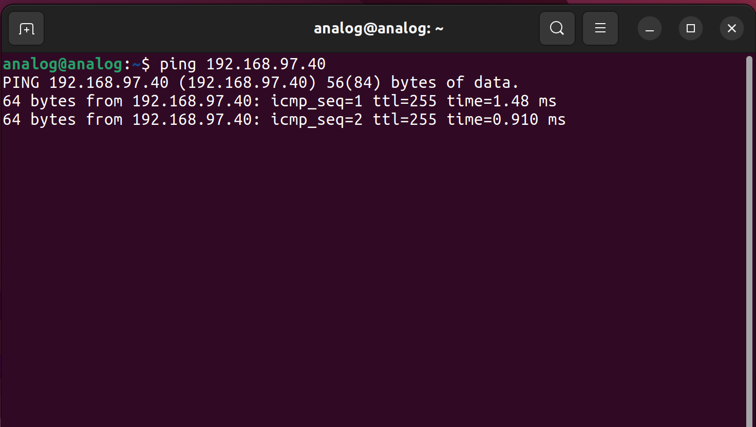
Ping the AD-SWIOT1L-SL board to verify connectivity:
ping 192.168.97.40
linux User Guide
Connect the AD-SWIOT1L-SL to your linux PC using the AD-T1LUSB2.0-EBZ
To communicate with the AD-SWIOT1L-SL board, you need to configure your linux PC’s network adapter with a static IP address in the same subnet as the board e.g 192.168.97.1/24.
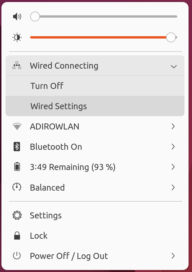
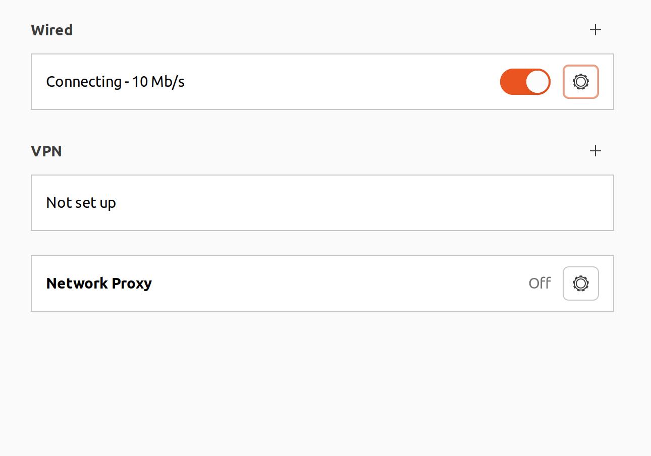
Configure linux Network Adapter
Identify the network interface corresponding to the AD-T1LUSB2.0-EBZ using the command:
Configure the network interface with a static ip address:
Verify you can ping the AD-SWIOT1L-SL board:
ping 192.168.97.40
The Scopy AD-SWIOT1L-SL Plugin
For detailed information on how to use the AD-SWIOT1L-SL Scopy plugin, including configuration, operation modes, and available instruments, please refer to the comprehensive Scopy SWIOT1L Plugin Documentation.
Using the IIO interface
The firmware is based on a no-OS implementation of the IIO framework from the linux kernel, which offers similar functionalities. Thus, the board may be configured through the use of pyadi-iio API.
In order to get the pyadi-iio drivers follow the next steps:
Clone the pyadi-iio repository:
git clone https://github.com/analogdevicesinc/pyadi-iio
Follow the installation steps provided in the pyadi-iio README.
### this might need changing once swiot is merged into main
Checkout the swiot branch:
git checkout swiot
Install the pyadi-iio package:
pip install .
SWIOT device configuration overview
This section provides a high-level overview of how the firmware manages device configuration. Detailed field device usage information is presented in the following sections. When powered, the SWIOT1L board operates in one of two states, each identified by a distinct IIO context:
Config: All channels are in a high impedance state. Users can configure channel functions and route each SWIOT1L channel to either the MAX14906 or AD74413R device using the swiot virtual device.
Note
When entering this state from the runtime mode, some of the device configurations will reset. The configuration selected in this context will help in generating the runtime IIO context.
Open the IIO context by running iio_info with the appropriate URI:
iio_info -u ip:192.168.97.40
The iio context should look similar to this:
Library version: 0.24 (git tag: c4498c2)
Compiled with backends: local xml ip usb serial
IIO context created with network backend.
Backend version: 1.1 (git tag: 0000000)
Backend description string: 192.168.97.40 no-OS swiot-rebase-lwip-eda9f736d-modified
IIO context has 2 attributes:
   ip,ip-addr: 192.168.97.40
   uri: ip:192.168.97.40
IIO context has 2 devices:
   iio:device0: swiot
      0 channels found:
      27 device-specific attributes found:
            attr  0: reset ERROR: No such file or directory (2)
            attr  1: serial_id value: 80a4-44044-1f003-2d8104ff-bf
            attr  2: mode value: config
            attr  3: mode_available value: config runtime
            attr  4: identify ERROR: No such file or directory (2)
            attr  5: ext_psu value: 1
            attr  6: signal_mse value: 32
            attr  7: ch0_enable value: 0
            attr  8: ch1_enable value: 0
            attr  9: ch2_enable value: 0
            attr 10: ch3_enable value: 0
            attr 11: ch0_function value: high_z
            attr 12: ch1_function value: high_z
            attr 13: ch2_function value: high_z
            attr 14: ch3_function value: high_z
            attr 15: ch0_device value: ad74413r
            attr 16: ch1_device value: ad74413r
            attr 17: ch2_device value: ad74413r
            attr 18: ch3_device value: ad74413r
            attr 19: ch0_function_available value: high_z voltage_out
               current_out voltage_in current_in_ext current_in_loop
               resistance digital_input digital_input_loop
               current_in_ext_hart current_in_loop_hart
            attr 20: ch1_function_available value: high_z voltage_out
               current_out voltage_in current_in_ext current_in_loop
               resistance digital_input digital_input_loop
               current_in_ext_hart current_in_loop_hart
            attr 21: ch2_function_available value: high_z voltage_out
               current_out voltage_in current_in_ext current_in_loop
               resistance digital_input digital_input_loop
               current_in_ext_hart current_in_loop_hart
            attr 22: ch3_function_available value: high_z voltage_out
               current_out voltage_in current_in_ext current_in_loop
               resistance digital_input digital_input_loop
               current_in_ext_hart current_in_loop_hart
            attr 23: ch0_device_available value: ad74413r max14906
            attr 24: ch1_device_available value: ad74413r max14906
            attr 25: ch2_device_available value: ad74413r max14906
            attr 26: ch3_device_available value: ad74413r max14906
      No trigger assigned to device
   trigger0: sw_trig
      0 channels found:
      No trigger on this device
Runtime: All channel functions are configured, and the devices are operational and out of reset. In this state, the devices can sample or output signals, report faults, and allow register read/write operations. Channel direction and functions remain fixed during runtime mode, except for the AD74413R’s diagnostic channels, which can still be modified.
Field Device Configuration and Usage
This section details how the IIO interface may be used to configure and sample data from the field devices. The system has the following IIO devices:
SWIOT Virtual Device
Field devices must have their channels configured before being used in the runtime context. This is done through the swiot virtual IIO device, which is present in both the config and runtime IIO contexts.
Device Attributes
reset: Write any value to reset the firmware. Cannot be read.
serial_id: Unique ID specific to the microcontroller. Read-only.
mode: Reflects the system’s state (config or runtime). Can be written to change state. Possible values are in
mode_available. Writing the current state value is a no-op. Invalid values are ignored.mode_available: Valid mode values:
config,runtime.identify: Write any value to blink LED2. Useful for identifying which board has a specific context (or IP) in a multi-board network.
ext_psu: Mirrors the external power supply switch. A value of 1 does not guarantee power supply connection or 156W capability. Read-only. Possible values:
0: Field devices powered only by LT8304 (via 24V terminal block) and/or LTC9111 (via SPoE)1: MAX14906 powered directly by external power supply
signal_mse: Single Pair Ethernet signal quality indicator. Read-only.
chX_enable: Channel-specific enable condition. X refers to the SWIOT1L terminal block channel number (0-based). When set to
0, the channel remains in high impedance state regardless of other attributes. Values:0or1.chX_function: I/O function for a SWIOT1L terminal block channel. Specific to AD74413R or MAX14906 depending on
chX_device. Possible values inchX_function_available. Important: SetchX_devicefirst, as the value is validated when written. Otherwise-EINVAL (-22)is returned.chX_function_available: Available values for
chX_function. Read-only.chX_device: Field device controlling the terminal block channel. Possible values in
chX_device_available.chX_device_available: Available values for
chX_device:ad74413r,max14906.
Configuration Example
In the pyadi-iio example script, channel functions are configured using the channel_enable, channel_config, and channel_device lists:
"""
Possible values:
- max14906 selected as device: input, output
- ad74413r selected as device: voltage_out, current_out,
  voltage_in, current_in_ext, current_in_loop,
  resistance, digital_input, digital_input_loop,
  current_in_ext_hart, current_in_loop_hart
"""
channel_config = ["voltage_in", "current_in_ext", "current_out", "output"]
# Possible values: 0, 1
channel_enable = [1, 1, 1, 1]
# Possible values: "ad74413r", "max14906"
channel_device = ["ad74413r", "ad74413r", "ad74413r", "max14906"]
This configuration means:
Channel 1: Routed to AD74413R channel 1, measuring input voltage
Channel 2: Routed to AD74413R channel 2, measuring input current
Channel 3: Routed to AD74413R channel 3, measuring voltage from current-limited output
Channel 4: Routed to MAX14906 channel 4, configured as digital output
To ensure config context is selected:
swiot.mode = "config"
Configuration sequence using swiot attributes:
swiot.ch0_device = channel_device[0]
swiot.ch0_function = channel_config[0]
swiot.ch0_enable = channel_enable[0]
swiot.ch1_device = channel_device[1]
swiot.ch1_function = channel_config[1]
swiot.ch1_enable = channel_enable[1]
swiot.ch2_device = channel_device[2]
swiot.ch2_function = channel_config[2]
swiot.ch2_enable = channel_enable[2]
swiot.ch3_device = channel_device[3]
swiot.ch3_function = channel_config[3]
swiot.ch3_enable = channel_enable[3]
Important
Set chX_device before chX_function, otherwise an error will occur.
The indexes in these lists correspond to the terminal block channel number (0-based).
When channels are configured, the firmware automatically places the corresponding parallel channel in high impedance to avoid conflicts.
Switching Contexts
To switch from config to runtime mode:
swiot.mode = "runtime"
After writing this attribute, the IIOD server restarts, causing the connection to drop and the IIO context to be destroyed. The new context must be recreated:
ad74413r = adi.ad74413r(uri=dev_uri)
max14906 = adi.max14906(uri=dev_uri)
adt75 = adi.lm75(uri=dev_uri)
swiot = adi.swiot(uri=dev_uri)
The runtime context also contains the field devices, which can be used to sample data.
Controlling the MAX14906
Direct Register Access
Device registers can be read or written using the IIO direct register access interface:
Reading:
value = max14906.reg_read(0x1)Writing:
max14906.reg_write(0x1, 0xff)
Warning
This method should be used with caution as it overwrites firmware settings. Updating an existing value requires a read→apply mask→write sequence.
Using Channel Attributes
The MAX14906 has the following IIO channels, corresponding to the 4 physical channels:
voltageX (input or output):
raw:
0or1, representing low/high state. For outputs:max14906.channels["voltage3"].raw = 1 # or 0
Can be read in both input and output modes:
state = max14906.channels["voltage3"].raw
scale: Constant value of
1offset: Constant value of
0current_limit (output only): Set from predefined values in
current_limit_available:max14906.channels["voltage3"].current_limit = 130
current_limit_available:
600,130,300,1200(mA)do_mode (output only): Configure output driver:
max14906.channels["voltage3"].do_mode = "High_side"
do_mode_available:
High_side,High_side_2x_inrush,Push_pull_clamp,Push_pullIEC_type (input only): Setup digital-IO input type
IEC_type_available:
Type_1_3,Type_2
Note
For comprehensive descriptions, refer to the MAX14906 datasheet.
Controlling the AD74413R
Direct Register Access
Device registers can be read or written using the IIO direct register access interface:
Reading:
value = ad74413r.reg_read(0x1)Writing:
ad74413r.reg_write(0x1, 0xff)
Warning
This method should be used with caution as it overwrites firmware settings.
Channel Configurations
Each AD74413R channel can be configured with one of these functions: voltage_out, current_out, voltage_in, current_in_ext, current_in_loop, resistance, digital_input, digital_input_loop, current_in_ext_hart, current_in_loop_hart.
1. Voltage Input
Creates one IIO channel:
Input voltage:
Attribute |
Description |
Access |
Shared |
|---|---|---|---|
raw |
Value 0-8191 (DAC code). Vout = (raw + offset) × scale (mV) |
R/W |
No |
scale |
Constant: 1.342 mV/LSB |
R |
No |
offset |
Constant: 0 |
R |
No |
sampling_frequency |
Samples per second (divided by enabled channels) |
R/W |
No |
sampling_frequency_available |
4800, 1200 (no filter); 20, 10 (filtered) |
R |
Yes |
2. Current Output
Creates two IIO channels:
Input voltage (measures voltage output by DAC):
Same attributes as Voltage Input configuration above.
Output current:
Attribute |
Description |
Access |
Shared |
|---|---|---|---|
raw |
Value 0-8191 (DAC code). Iout = (raw + offset) × scale (mA) |
R/W |
No |
scale |
Constant: 0.003051 mA/LSB |
R |
No |
offset |
Constant: 0 |
R |
No |
slew_en |
Enable slew rate control (uses slew_rate and slew_step) |
R/W |
No |
slew_rate |
Configure DAC output slew rate |
R/W |
No |
slew_rate_available |
Available slew_rate values |
R |
Yes |
slew_step |
Configure DAC output slew step |
R/W |
No |
slew_step_available |
Available slew_step values |
R |
Yes |
3. Voltage Output
Creates two IIO channels:
Input current (measures current output by DAC):
Attribute |
Description |
Access |
Shared |
|---|---|---|---|
raw |
Value 0-65535 (ADC code). I = (raw + offset) × scale (mA). Positive = sourced, negative = sinked |
R/W |
No |
scale |
Constant: 0.000762951 mA/LSB |
R |
No |
offset |
Constant: -32768 |
R |
No |
sampling_frequency |
Samples per second (divided by enabled channels) |
R/W |
No |
sampling_frequency_available |
4800, 1200 (no filter); 20, 10 (filtered) |
R |
Yes |
Output voltage:
Attribute |
Description |
Access |
Shared |
|---|---|---|---|
raw |
Value 0-8191 (DAC code). Vout = (raw + offset) × scale (mV) |
R/W |
No |
scale |
Constant: 1.22070 mV/LSB |
R |
No |
offset |
Constant: 0 |
R |
No |
slew_en |
Enable slew rate control (uses slew_rate and slew_step) |
R/W |
No |
slew_rate |
Configure DAC output slew rate |
R/W |
No |
slew_rate_available |
Available slew_rate values |
R |
Yes |
slew_step |
Configure DAC output slew step |
R/W |
No |
slew_step_available |
Available slew_step values |
R |
Yes |
4. Current Input Externally Powered
Creates one IIO channel:
Input current:
Attribute |
Description |
Access |
Shared |
|---|---|---|---|
raw |
Value 0-65535 (ADC code). I = (raw + offset) × scale (mA) |
R/W |
No |
scale |
Constant: 0.000381476 mA/LSB |
R |
No |
offset |
Constant: 0 |
R |
No |
sampling_frequency |
Samples per second (divided by enabled channels) |
R/W |
No |
sampling_frequency_available |
4800, 1200 (no filter); 20, 10 (filtered) |
R |
Yes |
5. Current Input Loop Powered
Creates two IIO channels:
Input current (measures current sourced by AD74413R):
Attribute |
Description |
Access |
Shared |
|---|---|---|---|
raw |
Value 0-65535 (ADC code). I = (raw + offset) × scale (mA) |
R/W |
No |
scale |
Constant: 0.000381476 mA/LSB |
R |
No |
offset |
Constant: 0 |
R |
No |
sampling_frequency |
Samples per second (divided by enabled channels) |
R/W |
No |
sampling_frequency_available |
4800, 1200 (no filter); 20, 10 (filtered) |
R |
Yes |
Output current (sets current limit sourced by AD74413R):
Attribute |
Description |
Access |
Shared |
|---|---|---|---|
raw |
Value 0-8191 (DAC code). Iout = (raw + offset) × scale (mA) |
R/W |
No |
scale |
Constant: 0.003051 mA/LSB |
R |
No |
offset |
Constant: 0 |
R |
No |
slew_en |
Enable slew rate control (uses slew_rate and slew_step) |
R/W |
No |
slew_rate |
Configure DAC output slew rate |
R/W |
No |
slew_rate_available |
Available slew_rate values |
R |
Yes |
slew_step |
Configure DAC output slew step |
R/W |
No |
slew_step_available |
Available slew_step values |
R |
Yes |
6. Current Input Loop Powered with HART Compatibility
The channels and their attributes are the same as Current Input Loop Powered mode.
7. Current Input Externally Powered with HART Compatibility
The channels and their attributes are the same as Current Input Externally Powered mode.
8. Resistance
Creates one IIO channel:
Resistance:
Attribute |
Description |
Access |
Shared |
|---|---|---|---|
raw |
Value 0-65535 (raw ADC result register value) |
R/W |
No |
sampling_frequency |
Samples per second (divided by enabled channels) |
R/W |
No |
sampling_frequency_available |
4800, 1200 (no filter); 20, 10 (filtered) |
R |
Yes |
9. Digital Input
Creates one IIO channel:
Voltage input:
Attribute |
Description |
Access |
Shared |
|---|---|---|---|
raw |
Value 0 or 1 (comparator output) |
R/W |
No |
scale |
Constant: 1 |
R |
No |
offset |
Constant: 0 |
R |
No |
threshold |
Threshold value in millivolts for comparator |
R/W |
No |
sampling_frequency |
Samples per second (divided by enabled channels) |
R/W |
No |
sampling_frequency_available |
4800, 1200 (no filter); 20, 10 (filtered) |
R |
Yes |
10. Digital Input Loop Powered
Creates two IIO channels:
Voltage input:
Attribute |
Description |
Access |
Shared |
|---|---|---|---|
raw |
Value 0 or 1 (comparator output) |
R/W |
No |
scale |
Constant: 1 |
R |
No |
offset |
Constant: 0 |
R |
No |
threshold |
Threshold value in millivolts for comparator |
R/W |
No |
sampling_frequency |
Samples per second (divided by enabled channels) |
R/W |
No |
sampling_frequency_available |
4800, 1200 (no filter); 20, 10 (filtered) |
R |
Yes |
Current output (sets current limit sourced by AD74413R):
Attribute |
Description |
Access |
Shared |
|---|---|---|---|
raw |
Value 0-8191 (DAC code). Iout = (raw + offset) × scale (mA) |
R/W |
No |
scale |
Constant: 0.003051 mA/LSB |
R |
No |
offset |
Constant: 0 |
R |
No |
slew_en |
Enable slew rate control (uses slew_rate and slew_step) |
R/W |
No |
slew_rate |
Configure DAC output slew rate |
R/W |
No |
slew_rate_available |
Available slew_rate values |
R |
Yes |
slew_step |
Configure DAC output slew step |
R/W |
No |
slew_step_available |
Available slew_step values |
R |
Yes |
Sampling Data from the AD74413R
Example: Sampling Buffered Data
The following example demonstrates how to use pyadi-iio to sample buffered data from the AD74413R:
ad74413r.rx_enabled_channels = ["voltage0"]
ad74413r.sample_rate = 4800
ad74413r.rx_buffer_size = 4800
data = ad74413r.rx()
You can change the sampling channel to another input channel:
ad74413r.rx_enabled_channels = ["current0"]
The channel must be configured appropriately in the SWIOT1L configuration. Samples are stored in the data array.