Sample Application
72V to 96V Light EV Basic System Application
Below diagram depicts the essential components needed when using this BMS reference design for basic electric 2-wheeler or 3-wheeler applications. Each block represents a component. Use the diagram as a guide to understand the system operation.
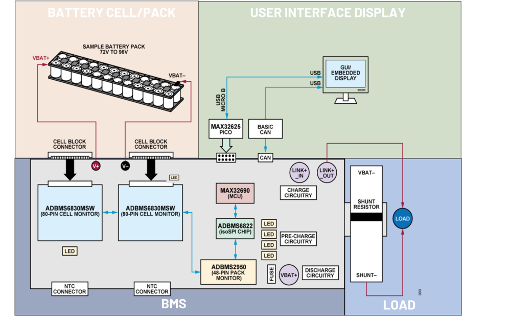
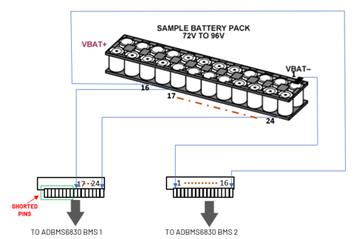
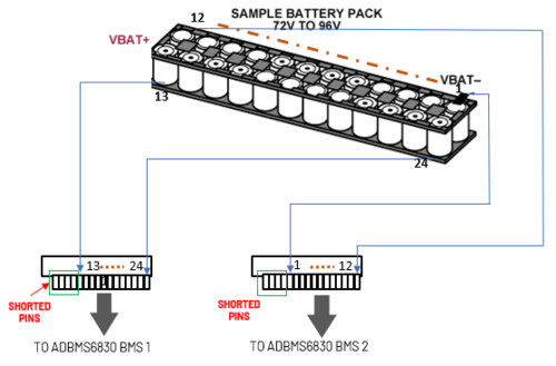
Battery Cell/Pack Block - This block is where your battery supply or source is located. There are two configurations on how to connect the battery cells to the BMS:
Note
The setup shown in this User Guide uses the single side depopulation method only in connecting/aligning the cell to the BMS. The dual side depopulation is not yet supported by the software.
BMS Block - This block is where the BMS Cell and Pack Monitoring and MCU control happens. This block is also responsible for the control of the Charging (if the battery needs to be charged) and Discharging (when the battery needs to deliver voltage output going to the load side).
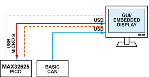
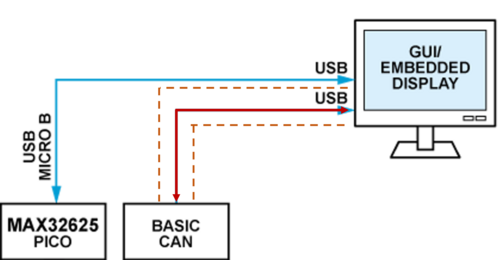
User Interface Display - This block is where the measurement, diagnosis, and status of the BMS are displayed. The Display can have two options (or you can use both):
UART Communication
Note
For the BASIC CAN setup, we use the PCAN-USB connector as our CAN interpreter. This product is not included in the AD-BMSE2E3W-SL Kit and needs to be purchased separately.
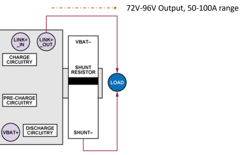
Load - This block is where you can place your external load. The voltage output at this level can vary from 72V to 96V with 50A to 100A range current capacity. The system implements a low side current sensing using Rshunt (sense resistor) where the VBAT- of the battery is connected to the upper end of the Rshunt bar and Shunt- is connected to the lower end of the Rshunt. The Shunt- will then be connected to the end of the load or the negative supply of the load.
After the set up for vehicle and load connection is done, you can now load the sample firmware for vehicle application.