Software Defined Instrumentation
Note
This is a work in progress.
Introduction
Theoretical content
theoretical background for instrumentation devices
ADALM2000 board overview, features, description
ADALM2000 connectivity
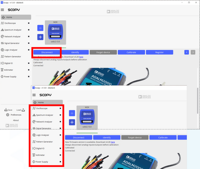
Scopy software overview and instruments description
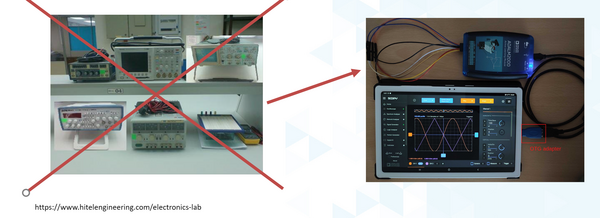
What is Software Defined Instrumentation?
A single device encapsulating more instruments used for measurements, signal generation, signal acquisition, etc., powered by a PC open-source software that allows the user to customize the measurements, since the software is residing more on the host PC/mobile device instead of on the instrument.
Bonus: it has a pocket size!
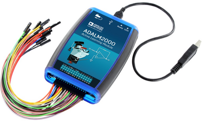
ADALM2000
The ADALM2000 (M2K) Advanced Active Learning Module is an affordable USB-powered data acquisition module, that can be used to introduce fundamentals of electrical engineering in a self or instructor lead setting.
With 12-bit ADCs and DACs running at 100 MSPS, brings the power of high-performance lab equipment to the palm of your hand, enabling electrical engineering students and hobbyists to explore signals and systems into the tens of MHz without the cost and bulk associated with traditional lab gear.
When coupled with Analog Devices’ Scopy™ graphical application software running on a computer, provides the user with high performance instrumentation.
Hands-on activity
By the end of this workshop, you will learn:
How to use a desktop Oscilloscope and Signal generator channels by operating a Network Analyzer, as well as Digital Pattern generator
How to interface an analog front end simple circuit with M2K channels
How to generate and display signals with the lab tools Analog Devices provides
Activities
breadboard Low-Pass filter implementation, two stages,
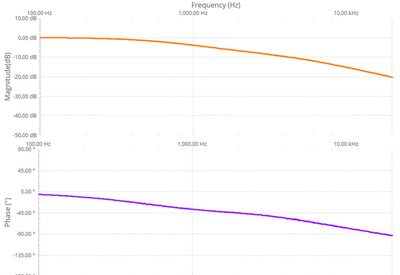
Bode plot visualisation,
usage of power supplies and scope inputs
SPI communication with ADALP2000 AD5626 part, DAC converter,
usage of Pattern Generator SPI interface and Scope channels for analog signals
Pre-requisites
Hands-on activity 1 - Scope and Signal generator channels – Cascaded LP filters
Materials
ADALM2000 Active Learning Module
Solder-less breadboard, and jumper wire kit
2 x 1 KΩ resistors
2 x 0.1 uF capacitors (marked 104)
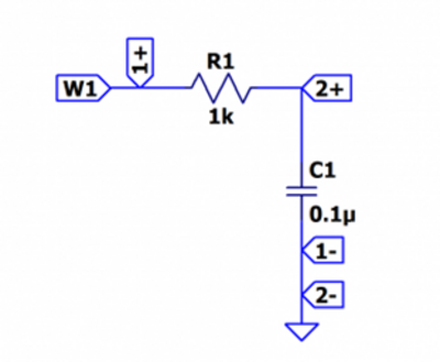
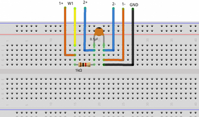
First Stage Filter
Hardware setup
Steps
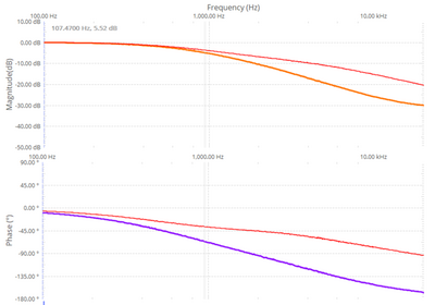
Open Network Analyzer
Set the sweep to logarithmic
Set the start frequency to 100Hz and stop to 20kHz
Set the magnitude axis between -50dB and 10dB
Set the phase axis between -180 and 90 degrees
Second stage filter
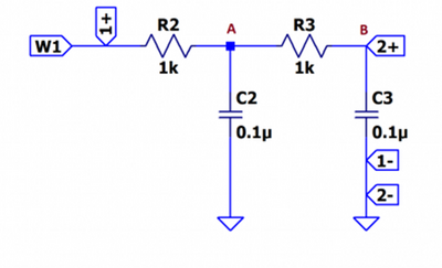
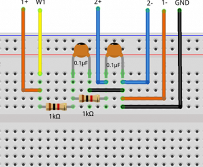
Steps:
Connect the Scope Channel 2 after the first RC group and do a single sweep
Take a signal snapshot to preserve the result as a reference
Connect the Scope Channel 2 after the second RC stage and perform another sweep
Hands-on activity 2 - Digital Pattern Generator and Scope – AD5626 component – SPI controlled and analog signal visualized using Scope
Materials
ADALM2000 Active Learning Module
Solder-less breadboard
Jumper wires
1 - AD5626 12-bit nanoDAC
1 x 2.2 KΩ resistor
1 x 0.001 uF capacitor(marked 102)
1 x 0.1 uF capacitor(marked 104)
1 x 10 uF capacitor
Theory of operation
SPI Transfer:
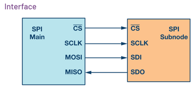
Hardware Setup
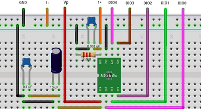
Steps
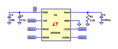
Connect the Vp power supply to the Vdd of the chip, set it to 5V
Connect the GND pin to the GND of the M2K
Beware not to connect the supply pins of the chip to the positive power of ADALM2000 and GND in a reversed order!
Connect the digital pins to the corresponding chip pins as shown in the schematic.
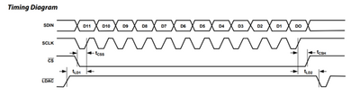
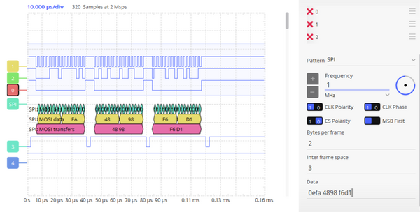
Configure the SPI interface in pattern generator to match the timing diagram of the AD5626 datasheet.
Pattern generator signals
DIO0 - /CS
DIO1 – SCLK
DIO2 – SDIN
DIO3 - /LDAC
DIO4 - /CLR
Setup
According to the time diagram, minimum SPI clock period is 30ns, set the SPI frequency to 1MHz
Set CLK polarity and Phase to 1
Set number of bytes per frame to 2
Configure the /LDAC and /CLR signals:
According to the AD5626 datasheet, the shift register contents are updated on the rising edge of /LDAC if /CLR is high.
Set the pattern of DIO4 (/CLR) as “Number” and enter the value 1.
/LDAC signal(DIO3) should have a rising edge before /CS falling edge and should be high as long as bits are transmitted serially.
With respect to the stated conditions, the DIO3 signal needs to be set as pulse type 100kHz frequency, Low number of samples equal to 5, High 75, for the set frequency of the SPI 1MHz.
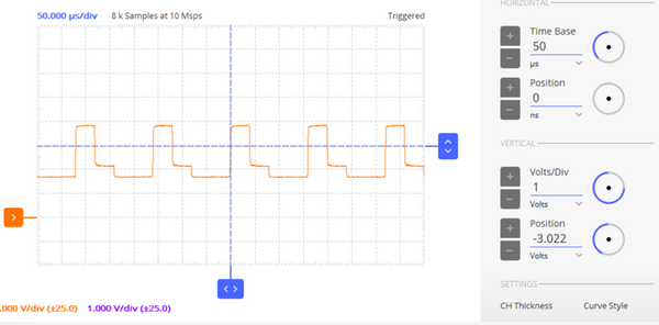
Scopy instruments setup
Open Scope instrument and connect Scope channel 1 to output pin of the AD5626 (pin 8 of the IC)
Enable the positive 5V Power supply
Set some values in the Data control of the pattern generator SPI configurator
Enable Channel 1 measurements to view the analog values
Change the initially transmitted values
Slide Deck and Booklet
Since this tutorial is also designed to be presented as a live, hands-on workshop, a slide deck is provided here:
A complete booklet of the hands-on activity is also provided, as a companion to following the tutorial yourself:
Takeaways
ADALM2000 is a very versatile tool suited to use in various applications:
Lab setups
Advanced measurements
Learning platforms
Research
Resources
ADALM2000 Wiki
ADALM2000 Lab Activities
Virtual classroom