AD-T1LUSB2.0-EBZ
USB2.0 to 10BASE-T1L Interface Board
Overview
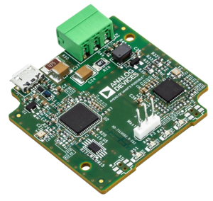
The AD-T1LUSB2.0-EBZ board is an interface between USB 2.0 and a 10BASE-T1L interface.
The current hardware configuration provides a straightforward architecture with a USB Ethernet Controller and MAC (LAN9500A) connected through MII to the ADIN1100 PHY.
The design also includes an EEPROM for saving and recalling MAC configurations and status LEDs to indicate link status (MAC) and user-programmable status flags from the PHY.
The AD-T1LUSB2.0-EBZ board doesn’t require any configuration to be functional and ready for use.
Features
Easy-to-use USB2.0 to 10BASE-T1L interface
Efficient data communication utilizing LAN9500A USB Ethernet Controller and MAC connected via MII to the ADIN1100 PHY
Onboard EEPROM for saving and recalling MAC configurations
LEDs indicating MAC link status and user-programmable PHY status flags
Operates without an external power supply, powered directly from the USB bus
Applications
Industrial Ethernet Application Development
Building Automation
System Architecture

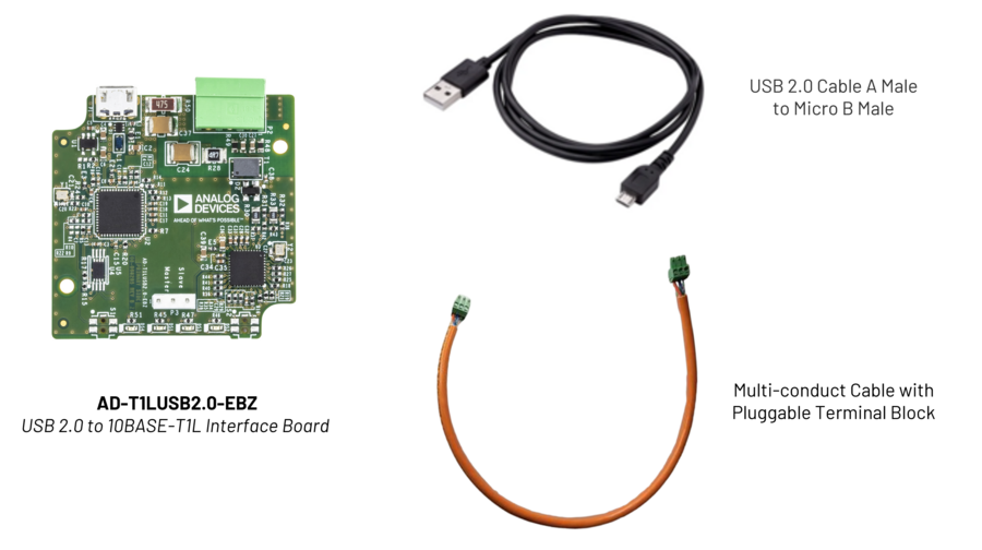
What’s Inside the Box?
Setup Examples
The AD-T1LUSB2.0-EBZ board is intended to be ready for use out of the box to quickly control any system with a 10BASE-T1L interface.
A couple of design examples that have a 10BASE-T1L interface that will work together with the AD-T1LUSB2.0-EBZ board are:
AD-SWIOT1L-SL - Software-configurable Analog and Digital I/O with 10BASE-T1L Evaluation and Development Platform
AD-APARD32690-SL - Arduino Form-factor Development Platform Based on MAX32690 ARM Cortex-M4 Microcontroller
Note
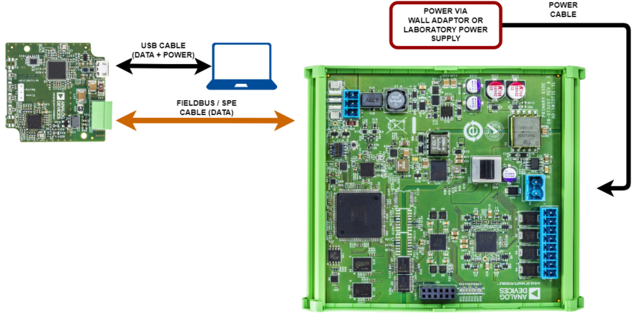
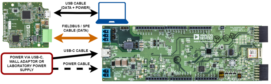
The AD-T1LUSB2.0-EBZ will send or receive data only over a FROFIBUS/SPE cable, so any design with a 10BASE-T1L interface will need to be powered separately.
AD-SWIOT1L-SL Interfacing
AD-APARD32690-SL Interfacing
Network Testing
When the AD-T1LUSB2.0-EBZ board is connected to a computer via a USB cable, a new network interface should be available.
This can be verified by running on a shell terminal the ``ipconfig`` command on a Windows system or ``ifconfig`` on a Linux system.
The new network configuration which corresponds to the following example:
Ethernet adapter Ethernet 3:

   Connection-specific DNS Suffix  . :
   Link-local IPv6 Address . . . . . : fe80::5079:d4ec:5a1:6387%63
   Autoconfiguration IPv4 Address. . : 169.254.193.171
   Subnet Mask . . . . . . . . . . . : 255.255.0.0
   Default Gateway . . . . . . . . . :
After this we can run the ping command as ping -t 169.254.193.171 to
obtain the following response if everything works properly:
Pinging 169.254.193.171 with 32 bytes of data:
Reply from 169.254.193.171: bytes=32 time<1ms TTL=128
Reply from 169.254.193.171: bytes=32 time<1ms TTL=128
Reply from 169.254.193.171: bytes=32 time<1ms TTL=128
Reply from 169.254.193.171: bytes=32 time<1ms TTL=128
Reply from 169.254.193.171: bytes=32 time<1ms TTL=128
Reply from 169.254.193.171: bytes=32 time<1ms TTL=128
Reply from 169.254.193.171: bytes=32 time<1ms TTL=128
Reply from 169.254.193.171: bytes=32 time<1ms TTL=128
Reply from 169.254.193.171: bytes=32 time<1ms TTL=128
Reply from 169.254.193.171: bytes=32 time<1ms TTL=128
In this way, we can confirm that the connection between a computer and the AD-T1LUSB2.0-EBZ board works as expected.
Design and Integration Files
Download
AD-T1LUSB2.0-EBZ Design Support Package
Schematic
PCB Layout
Bill of Materials
Allegro Project
Support
Analog Devices will provide limited online support for anyone using the reference design with Analog Devices components via the EngineerZone Reference Designs forum.